


PS-4600 Series User Manual
125
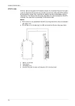
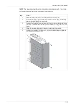
Interface Module Position
The figure shows the slot positions:
1
Slot 2 (IF2)
2
Slot 1 (IF1)
NOTE:
Take into account the interface module restrictions as identified in the table
below. After replacing or installing an interface module, restore BIOS default settings
via Exit Menu
(see page 103)
.
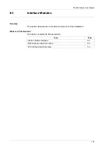
The table provides the possible positions of the interface modules in the slots:
Industrial Personal Computer
Part Number
Slot 1
Slot 2
UPS Interface Board
(see page 132)
PFXZPSIUUPM2
x
–
COM Expansion Board
(see page 129)
PFXZPSIUCMR42
x
x
Содержание PS-4600 Series
Страница 1: ......
Страница 12: ...About the Book 12...
Страница 14: ...General Overview 14...
Страница 26: ...Important Information 26...
Страница 56: ...Implementation 56...
Страница 72: ...Industrial Personal Computer Connections 72...
Страница 78: ...Configuration of the BIOS 78 Platform Information The figure shows the Main submenu...
Страница 118: ...Hardware Modifications 118 The figure shows the dimensions of the UPS battery unit...
Страница 170: ...Hardware Modifications 170...
Страница 172: ...Installation 172...
Страница 192: ...192...
Страница 196: ...After sales service 196...


