FP2500-T41 User Manual
Specifications
2-9
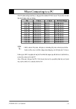
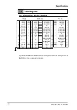
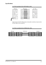
2-4-2 Pin Connections for the SIO Interface Cable
1
CD
Output
2
RD
Output
3
SD
Input
4
DTR
Input
5
GND
--
6
DSR
Output
7
RS
Input
8
CS
Output
9
NC
--
FG
FG
--
Input
CD
1
Input
RD
2
Output
SD
3
Output DTR 4
--
GND 5
Input
DSR 6
Output
RS
7
Input
CS
8
Input
RI
9
CD
1
RD
2
SD
3
DTR 4
GND 5
DSR 6
RS
7
CS
8
RI
9
FG
9
1
CD
2
RD
3
SD
4
DTR
5 GND
6
DSR
7
RS
8
CS
9
NC
FG FG
PC side
FP side
SIO cable
Signal names for the FP's SIO interface are designed to match the same pin order as
the SIO interface on a standard PC.
2-4-3 Pin Connections for the USB Interface Cable
1 +5VIN
Input
2 USB-
Input/Output
3 USB+
Input/Output
4 GND
Input/Output
1 +5VIN
Input
2 USB-
Input/Output
3 USB+
Input/Output
4 GND
Input/Output
Output
+5VIN
1
Input/Output USB-
2
Input/Output USB+
3
Input/Output GND
4
Output
+5VIN
1
Input/Output USB-
2
Input/Output USB+
3
Input/Output GND
4
FP side
USB cable
PC side
Содержание FP2600-T41
Страница 1: ...FP2600 T41 User Manual Digital Electronics Corporation...
Страница 45: ...Touch Panel Commands 4 8 FP2600 T41 User Manual MEMO...
Страница 53: ...Maintenance FP2600 T41 User Manual 6 4 MEMO...
Страница 57: ...iv FP2600 T41 User Manual MEMO...

