9.45, 9.45i Treadmill
Page 40
Procedure 6.4 - Replacing the Limit Switches, Actuator Shaft
or Switch Bracket (1L Units)
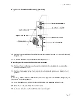
The three limit switches and the actuator shaft are mounted on the switch bracket (see Diagram
6.4).
WARNING
Always turn off the circuit breaker and unplug the treadmill before you remove the treadmill hood.
Procedure
1.
Remove the hood as described in Procedure 5.1 of the Residential Treadmill Service
Manual.
2.
If you are not removing the upper limit switch, skip to step 6.
Removing the Upper Limit Switch
WARNING
When power is applied to the treadmill, the wires connected to the upper and lower limit switches
carry line voltage. Turn off the treadmill and unplug the power cord from the wall outlet before
you perform the following steps.
3.
Carefully remove the red wires from the upper limit switch.
Note:
See diagram 6.6 for limit switch wiring
4.
Remove the screws and washers that secure the limit switch to the switch bracket.
5.
If you are not removing the lower limit switch, skip to step 9.
Removing the lower Limit Switch
6.
Carefully remove the black wires from the down limit switch.
7.
Remove the screws and washers that secure the limit switch to the switch bracket (see
Diagram 6.4).
8.
If you are not removing the zero sense switch, skip to step 12
Removing the Zero Sense Switch
9.
Carefully remove the blue wires from the zero sense switch.
Содержание 9.45
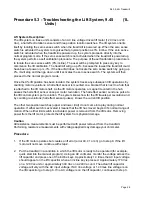
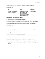
Страница 55: ...9 45 9 45i Treadmill Page 55 Wiring Diagram 7 1 9 45 1L Unit...
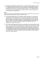
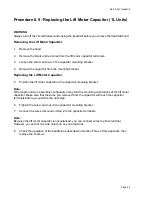
Страница 56: ...9 45 9 45i Treadmill Page 56 Block Diagram 7 2 9 45 1L Units...
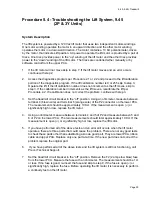
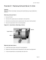
Страница 57: ...9 45 9 45i Treadmill Page 57 Wiring Diagram 7 3 9 45 2P 3Y Units...
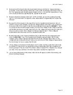
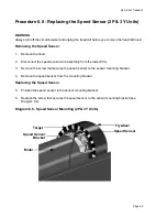
Страница 58: ...9 45 9 45i Treadmill Page 58 Block Diagram 7 4 9 45 2P 3Y Units...

