9.45, 9.45i Treadmill
Page 38
14. Choose one:
If...
Then...
Otherwise...
You are replacing the
Continue with the next
Skip to Step 18
rotation sensor
step
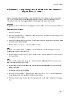
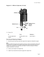
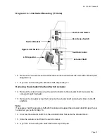
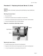
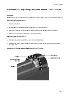
15. Remove the screw and washer that secure the rotation sensor to the sensor bracket (see
Diagram 6.3).
16. Position the rotation sensor at its mounting location.
17. Position the screw and washer that secure the rotation sensor to the sensor bracket. Torque
the screw to 8 in-lbs.
18. Choose one:
If...
Then...
Otherwise...
You are replacing the lift
Continue with the next
Skip to Step 22
motor you removed
step
earlier in this procedure
Removing and Replacing the Rotation Sensor Bracket
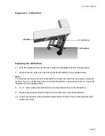
19. Remove the two nuts that secure the sensor bracket to the lift motor.
20. Position the sensor bracket removed in the previous step on the lift motor.
21. Replace the two nuts that secure the sensor bracket to the lift motor.
Replacing the Lift Motor
22. Position the magnet hub on the lift motor so that it is flush with the speed sensor bracket.
23. Replace the set screw that secures the magnet hub to the lift motor.
24. Extend the lift motor actuator 1/2” by turning the magnet hub.
Note:
To extend the lift motor actuator faster, place a screwdriver shaft in the lower mounting hole of
the lift motor and turn the screwdriver handle.
25. Position the lift motor at its mounting location.
Note:
When you perform Step 26, replace the lower screw and nut first.
26. Replace the two shoulder screws and nuts that secure the lift motor to the treadmill frame.
Содержание 9.45
Страница 55: ...9 45 9 45i Treadmill Page 55 Wiring Diagram 7 1 9 45 1L Unit...
Страница 56: ...9 45 9 45i Treadmill Page 56 Block Diagram 7 2 9 45 1L Units...
Страница 57: ...9 45 9 45i Treadmill Page 57 Wiring Diagram 7 3 9 45 2P 3Y Units...
Страница 58: ...9 45 9 45i Treadmill Page 58 Block Diagram 7 4 9 45 2P 3Y Units...

