P
RO
V
U
™ PD7000 Temperature Meter
Instruction Manual
14
Signal Connections
Signal connections are made to a three-terminal
connector labeled SIGNAL.
Thermocouple and RTD
Connections
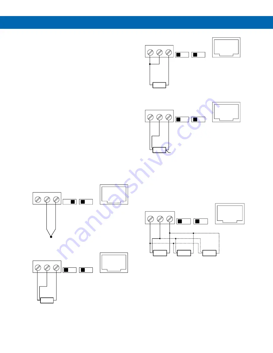
The following figures show examples for
thermocouple and RTD connections.
The TYPE selector switch must be set to the proper
position for the meter to accept the selected RTD or
TC input.
The RANGE selector switch is used to select 100-
ohm platinum or 10-ohm copper RTD. The 1000-ohm
platinum RTD input uses the same setting as the 100-
ohm RTD.
The input type is selected using the
Setup
menu.
The selected thermocouple input must correspond to
the thermocouple sensor and wire type used.
The meter accepts two, three, or four-wire RTDs. The
three-wire RTD connection has built-in lead wire
compensation.
Lead wire compensation for two-wire RTDs can be
applied using the
Adjust
menu. See the
Advanced
Features Menu
on page
30
.
The four-wire RTD connection is similar to the three-
wire. One of the leads of a four-wire RTD is not
connected, and may be clipped off.
The three-wire connection provides sufficient lead
wire compensation to obtain accurate readings even
with long leads.
Figure 11. Thermocouple Input Connections
Figure 12. Three-Wire RTD Input Connections
Figure 13. Two-Wire RTD Input Connections
Figure 14. Four-Wire RTD Input Connections
Connections for Averaging RTD
Sensors
To obtain the average temperature from 2 to 10 RTD
sensors, connect all the sensors in parallel and select
the number of sensors in the
RTD Total
(
rtdtot
)
menu. See the
Advanced Features Menu
on page
30
.
Figure 15. Average Temperature RTD Input
Connections
Modbus RTU Serial
Communications
Serial communications connection is made to an
RJ45 connector labeled M-LINK. For interfacing to the
P
RO
V
U
, use the PDA1232 for RS-232 or the PDA1485
for RS-485. The same port is used for interfacing with
all expansion modules (
i.e
. external relays, digital
I/O).
SIGNAL
EXC
T+
COM
1
2
3
RTD
TYPE
TC
100
RANGE
10
M-LINK
1
2
3
4
5
6
7
8
-
+
TC
RTD
Sensor
SIGNAL
EXC
T+
COM
1
2
3
RTD
TYPE
TC
100
RANGE
10
M-LINK
1
2
3
4
5
6
7
8
RTD
Sensor
SIGNAL
EXC
T+
COM
1
2
3
RTD
TYPE
TC
100
RANGE
10
M-LINK
1
2
3
4
5
6
7
8
RTD
Sensor
SIGNAL
EXC
T+
COM
1
2
3
RTD
TYPE
TC
100
RANGE
10
M-LINK
1
2
3
4
5
6
7
8
NC
RTD1
SIGNAL
EXC
T+
COM
1
2
3
RTD
TYPE
TC
100
RANGE
10
M-LINK
1
2
3
4
5
6
7
8
RTD2
RTD3


