Operation and installation manual
Page 28 of 96
(PVI-STRINGCOMB (-S, -MC, -S-MC) - Rev:1.0)
6.3 Description of the sections
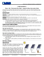
6.3.1 Input connections (Ref.§6.1 items A and B, Figure 6-1)
It is possible to connect a maximum of 20 strings using the two input boards A
and B respectively dedicated to the positive and negative pole. The current that
flows through each channel is detected using special sensors (these sensors are
only installed on board "A"). The status of every fuse positioned to protect each
string (Fuse Status) is also checked. The system also measures the global
voltage of the photovoltaic field via these boards. Any anomalies in the system
will be displayed via the special monitoring software or
3
on the Aurora inverter's
display.
Figure 6-4: Terminal boards for positive strings input (A) and negative strings
input (B) + string fuse carrier
3
A computer is needed (not supplied)
A
B