Operation and installation manual
Page 52 of 96
(PVI-STRINGCOMB (-S, -MC, -S-MC) - Rev:1.0)
9.3.10 Earth connection
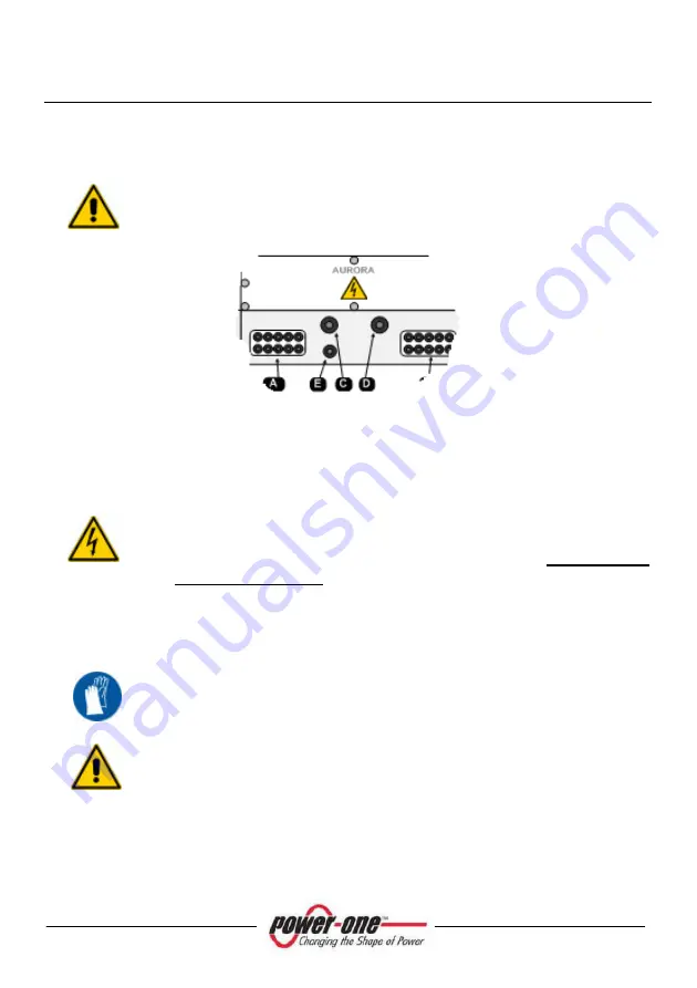
Ground the earth terminal, passing the wire through the gland
indicated as "E".
Figure 9-17: Cable gland for ground connection
9.3.11 Check on inverter side connections
Before continuing with the next steps, check that:
(A) The switches/isolators of the DC voltage are OFF (in the
inverter)
(B) The wires coming from the inverter are not live! (check directly
with a voltage meter)
9.3.11.1 Connection of the positive output wire (+)
After checking the above, pass the wire (positive pole) coming from
the inverter through the cable gland “C” of the Figure 4-3 and connect
it, with the screw and nut, to the “+” bar.
The copper bar for the positive pole features a threaded bore and
M10 bolt with washers (supplied) (Ref. §Appendix A: Technical Data).
Check that the lug is tight.


