background image


39 


4000T 


4.


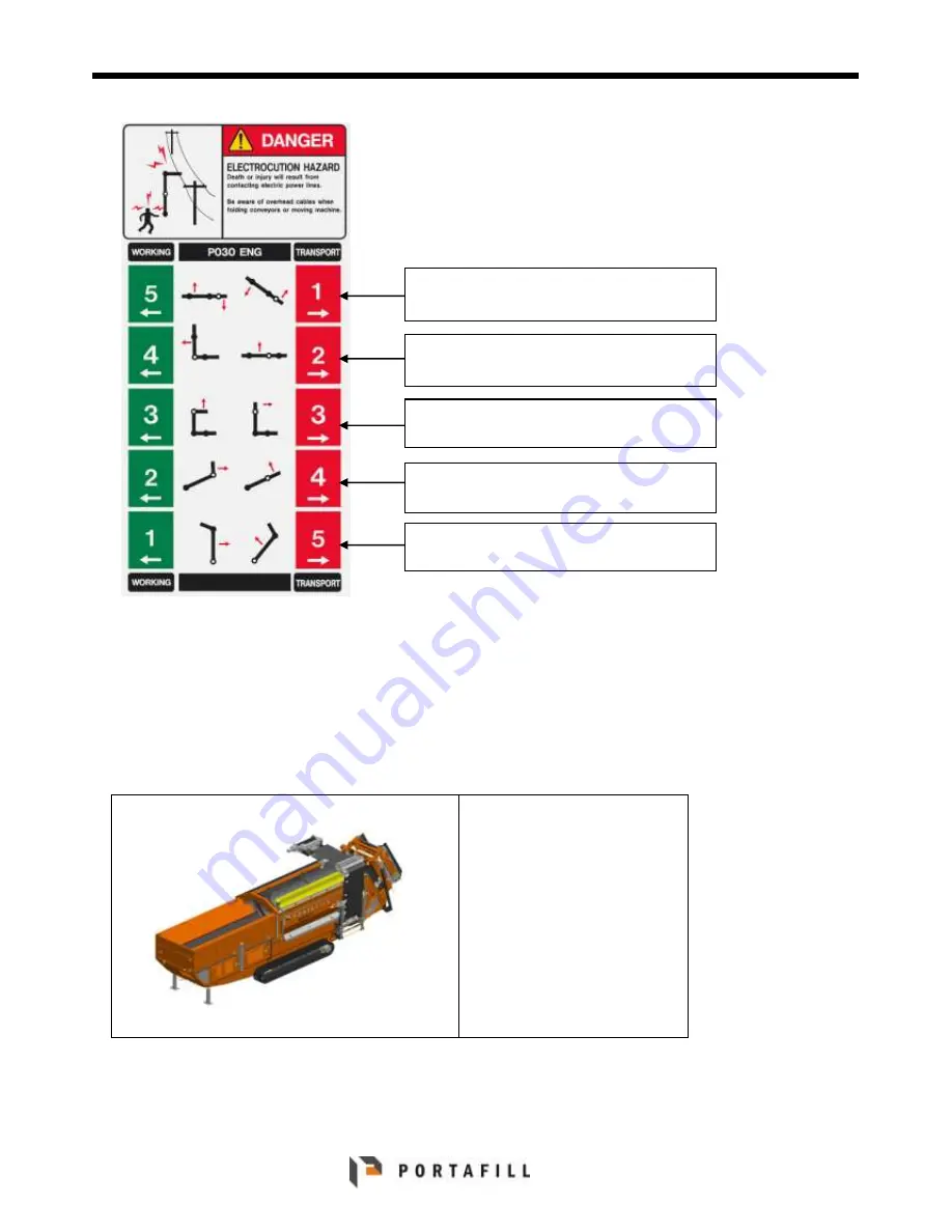
The stickers show a series of numbers and the 
numbers  are  designed  to  show  you  the 
sequence of steps needed to get the machine 
from  a  transport  position  to  a  working 
position.  

5.


The  numbers  with  a  green  background  show 
the steps to unfold the conveyors to working 
position. The numbers with a red background 
show  the  steps  to  fold  the  conveyors  to 
transport position.   


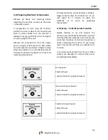
Machine in transport position 

Wing Conveyor 

 Raise / lower 

Wing Conveyor – Mid Section 

 Fold / Unfold 

Wing Conveyor - Head Section  

Raise / Lower 


Oversize Conveyor - Head Section  

Raise / Lower  


Oversize Conveyor – Tail Section 

 Fold / Unfold 


Содержание 4000T

Страница 1: ...ii 4000T 4000T USER MANUAL...

Страница 2: ...at every operator is properly trained and thoroughly familiar with all of the controls before operating the machine A replacement manual is available from your Authorised Dealer or by contacting Porta...

Страница 3: ...e Serial Number T 140 Complies with the provisions of the following EC Directives 2006 42 EC Machine Safety Directive 2004 108 EC Electromagnetic Compatibility Directive 2005 95 EC Low Voltage Directi...

Страница 4: ...duct or event unless otherwise noted Complying with all applicable copyright laws is the responsibility of the user No part of this document may be reproduced or transmitted in any form or by any mean...

Страница 5: ...D TECHNICAL INFO 23 2 1 MACHINE SPECIFICATION AND IDENTIFICATION 23 2 2 SPECIFICATION 24 2 3 WORKING DIMENSIONS 25 2 4 TRANSPORT DIMENSIONS 26 2 5 SOUND PRESSURE LEVELS 27 2 5 1 Conclusions 27 SECTION...

Страница 6: ...HE RETURN LINE FILTER 59 5 10 AIR CLEANER MAINTENANCE 59 5 11 FUEL SYSTEM 60 5 12 BATTERY ROUTINE CHECKS 61 5 13 MAIN CONTROL PANEL WARNING LIGHTS 61 5 14 AIR BREATHER RESTRICTION OPTIONS 62 5 15 TRAC...

Страница 7: ......

Страница 8: ...9 4000T...

Страница 9: ...guarding to be removed DO NOT OPERATE MACHINERY UNTIL ALL GUARDING IS REPLACED AND SECURED Always read and understand the Operator s Manual before Operation Service Maintenance of the machine For you...

Страница 10: ...manual and safety signs on your machine may also be available in other languages see your authorised dealer to order Sections in your operator s manual are placed in a specific order to help you unde...

Страница 11: ...tices on or near the machine that may result in personal injury if proper precautions are not taken 1 6 Safety Instructions and Applications The machine has been specifically designed to separate aggr...

Страница 12: ...on the machine while the machine is in operation or moving NEVER make any modifications to the machine that may compromise safety ALWAYS ensure that all the decals stickers on the machine are kept cle...

Страница 13: ...onal interruptions Care must be exercised not to abuse the machine or affect its performance in any way Failure to properly maintain and use the machine may result in property damage including machine...

Страница 14: ...maintenance 1 11 Safety When Working with Hazardous Chemicals ALWAYS handle hazardous chemicals with care Direct exposure to hazardous chemicals can cause serious injury Potentially hazardous chemica...

Страница 15: ...r check battery charge by placing a metal object across the posts Use a voltmeter or hydrometer Always remove grounded battery clamp first and replace it last CAUTION Sulfuric acid in battery electrol...

Страница 16: ...port ALWAYS ensure that when transporting the machine that the vehicle being used is specified for hauling the gross weight of the machine Failure to use a transportation vehicle not specified to haul...

Страница 17: ...hen moving the machine ALWAYS make sure that the ground the machine is travelling over is capable of carrying the weight if the machine NEVER attempt to track a machine across a slope Doing so can cau...

Страница 18: ...ted with two interlock switches on the main screen side door and the feeder The side door needs to be fully closed and the switch engaged to ensure that the machine starts If the door is not closed pr...

Страница 19: ...rs all unreadable or missing labels should be replaced with new ones before operating machine Each Label is part numbered and positioned as shown below so if and when required your local dealer can be...

Страница 20: ...4 0 0 0 T 21 P 006ENG P 008ENG P 009ENG P 010ENG P 011ENG P 014ENG P 016ENG P 018ENG P 027ENG P 029ENG P 036ENG...

Страница 21: ...Each machine is fitted with a serial plate which is located inside the power pack near the starter panel this plate will list the Serial No Date of Manufacture When ordering replacement spare parts i...

Страница 22: ...and Identification This Section of the Manual will help you identify the Various Controls and functions of the different Assembly Modules of the machine and will help you identify the terminology use...

Страница 23: ...Collection Conveyor 1200 mm wide flat belt Feeder Conveyor 900mm wide flat belt Variable speed Feeder drive sensitive to drum load HOPPER Hopper available with optional hydraulically tipping grid wit...

Страница 24: ...4 0 0 0 T 25 2 3 Working Dimensions...

Страница 25: ...sions All drawing dimensions approximate and in millimetres Portafill International reserves the right to alter the specification of this machine without notice Detailed dimensional drawings can be re...

Страница 26: ...e at least 10dB below the measured noise levels when the plant was running and did not influence the recorded noise levels Recorded at 1m and 5m dBL A 5min Not to scale Result noted below 2 5 1 Conclu...

Страница 27: ...ies and within the recycling industry It is capable of producing a range of product sizes as the trommel drum can be replaced with a different sized drum to cater for different finished product size r...

Страница 28: ...angle onto the grid section Material should be rolled onto the grid section from as low an angle as possible allowing the material to slide off The oversized material from the grid bars should not be...

Страница 29: ...breakdowns These operating instructions must be followed at all times when operating the Portafill 4000T Please refer to the safety section of the manual for important information on the safe operatio...

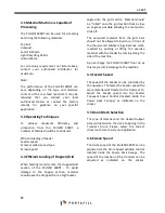
Страница 30: ...hrottle Lever This is located inside Powerpack Canopy beside Control Panel see photo below at idle as indicated by the sign 4 To start the machine turn the ignition key clockwise A warning siren will...

Страница 31: ...chine Layout Front Back Sides RIGHT HAND and LEFT HAND sides are determined by the direction of the material flow through the machine The following direction will be used throughout the manual FRONT B...

Страница 32: ...sius allow the machine to run on idle speed for 15 minutes to allow the hydraulic oil to reach its operating temperature 5 On days where the air temperature is above 5 degree Celsius allow the machine...

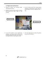
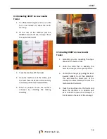
Страница 33: ...in position secure the oversize conveyor by attaching the locking assembly 4 5 Loading 4000T on Low Loader Trailer 1 Essentially you are repeating the steps above but in reverse order 2 Undo the latc...

Страница 34: ...n Push Button Left Hand Track Reverse Arrow Indication Push Button Right Hand Track Reverse Arrow Indication Push Button Track Mode On Track Mode Off 4 7 Operating Instructions This radio system is a...

Страница 35: ...where the air temperature is above 5 degree Celsius allow the machine to run on idle speed for 5 minutes to allow the hydraulic oil to reach its operating temperature 4 9 Set Up Control Levers Functio...

Страница 36: ...cation where you wish to screen material 3 The Control Levers for raising the machine on the jacklegs is located near the engine compartment 4 Lower the jacklegs to the ground to raise the machine to...

Страница 37: ...11 Set Up Conveyors to Working Position 1 Observe all safety and warnings before operating the machine 2 The wing conveyors and oversize conveyor can be moved into their working positions via the main...

Страница 38: ...rs with a green background show the steps to unfold the conveyors to working position The numbers with a red background show the steps to fold the conveyors to transport position Machine in transport...

Страница 39: ...in and release the oversize conveyor Do this on both sides of the conveyor Remove the locking pin and release the wing conveyor transport bracket Do this on both sides of the conveyor Adjust angle of...

Страница 40: ...4 0 0 0 T 41 Remove the retaining clip and remove the locking pin from the conveyor tail section Insert the locking pin into the top hole to place the conveyor into working position...

Страница 41: ...switches named CIRCUIT 1 and CIRCUIT 2 Circuit 1 controls the Feeder Collection and Oversize Conveyor Circuit 2 controls the Wing Conveyor and Screen 5 Turn both these switches clockwise to the ON po...

Страница 42: ...enclosure Feeder Conveyor Speed Faster Slower Located inside the engine enclosure 9 To adjust the speed of the conveyors turn the speed control clockwise or anticlockwise as indicated by the relevant...

Страница 43: ...the drum You can find two switches in the engine compartment One is a high pressure switch and one is a low pressure switch Each switch can be adjusted to allow different pressures To adjust the butto...

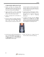
Страница 44: ...tches until you find the desired and optimum screening performance 4 14 Moving the 4000T about Site 1 Observe all safety and warnings before moving the machine NEVER track the machine across a slope a...

Страница 45: ...bottom button Note the machine can only track in straight lines with this button 13 If you wish to remove the dog lead remote then to make sure the machine will work you need to attached the blanking...

Страница 46: ...are designed to show you the sequence of steps needed to get the machine from a working position to a transport position 8 The numbers with a red background show the steps to fold the conveyors to tr...

Страница 47: ...48 4000T Machine in working position Remove the locking pin from working position...

Страница 48: ...4 0 0 0 T 49 Insert the locking pin into the bottom hole to place the conveyor into transport position Raise or lower oversize conveyor if required...

Страница 49: ...p the wing conveyor transport bracket and insert the locking pin Do this on both sides of the conveyor Clamp the oversize conveyor transport bracket and insert the locking pin Do this on both sides of...

Страница 50: ...the Portafill 4000T Warning The machine MUST be switched off and isolated with the ignition keys removed and stored in safe place Before making any adjustments All maintenance must be carried out by...

Страница 51: ...Pins Check Replace Hydraulic Pipes Check for leaks Replace Engine Area Engine Oil Check Level Top Up Hydraulic Oil Check Level Top Up Diesel Fuel Check Level Top Up Drum Screen Mesh Check Wear Replace...

Страница 52: ...r service on engine as per manufacturer s instructions Engine Speed Check Air Cleaner Element Air Pre Cleaner Clean Out Engine Radiator Remove guard Clean out with air Battery Electrolyte Level Check...

Страница 53: ...ry out Daily 10 50 100 and 250 Hour Service Engine Engine Oil Change Engine Oil Filter Change Fuel Filter Change Air Filter Inner Element Change Hydraulic Return Filter Change Track Gear Box Oil Check...

Страница 54: ...is recommended that you check engine oil level daily Add oil if level is below recommended level Never attempt to operate machine when oil level is below recommended level 5 4 Hydraulic Ram Maintenan...

Страница 55: ...lowing procedures Ensure extreme cleanliness at all times when working on the hydraulic system If the hydraulic oil requires topping up on a regular basis check all hoses and hydraulic parts for leaks...

Страница 56: ...4 0 0 0 T 57 5 6 Hydraulic Tank Maintenance Hydraulic Return Filter Filler Cap Suction Filter Hydraulic Shut off Valve Level Gauge...

Страница 57: ...the hydraulic oil It will be easier to change the oil if it is at normal operating temperature 3 Slowly unscrew the filler cap to release any pressure build up 4 Place a suitable sized container under...

Страница 58: ...the filter element 5 Wash out the filter cover with a dry air hose Do not use a rag 6 Replace the filter and replace cover and retighten bolts 5 10 Air Cleaner Maintenance The Air Cleaner is situated...

Страница 59: ...ted on the right hand side to the rear of the machine 2 The fuel level gauge is shown above 3 When required to refuel the machine clean any dirt away from fuel cap to avoid dirt getting into fuel syst...

Страница 60: ...light and engine pre heat indicator light 1 Battery Charge Warning Light Lights upon start up only if it fails to light there is a fault in the charging circuit Stop engine and check circuit 2 Oil Pr...

Страница 61: ...CB then light remains on continuously until fault has been repaired If Air Filter Override link is out and it continues to receive a fault signal the light stays on for 30 minutes After 30 minutes the...

Страница 62: ...s Wear can occur on the inside diameter of the Track Roller It is normally sufficient to measure only the rollers closest to the Sprocket and Idler as these will have the highest rates of wear Track A...

Страница 63: ...possible solutions that may occur during the life time of the Tracks One Track not operating or operating slower than the other Check the same size motor has been fitted to both Tracks Excessive Oil l...

Страница 64: ...4 0 0 0 T 65...

Страница 65: ...ly off line and in this case it is necessary to adjust the alignment of the belt If the conveyor is running off to the left hand side either extend the left hand side of the drum or retract the right...

Страница 66: ...en retained nut A and bearing nuts C and then adjust bolt B to tighten or align the conveyor belt Tighten the bearing nuts C and nut A when the adjustment is over 5 19 3 Oversize Conveyor The oversize...

Страница 67: ...ia the drive drum Loosen the Fixing Nuts A and C Turn the Retaining Nuts B to adjust the belt If the conveyor belt is running off to the left then tighten the left hand adjuster or loosen the right ha...

Страница 68: ...tenance Checks When performing any maintenance on the Screen you should ensure machine is turned off and keys are removed from control box to a safe location It is also recommended that you clean the...

Страница 69: ...can be placed back into the 4000T Ensure that the drum is placed in the machine so that the drum channel rests on the trommel guide wheels and that the drive sprocket is located in the drum sprocket...

Страница 70: ...4 0 0 0 T 71 Sprocket Alignment Nuts Turn clockwise moves drive Turn anticlockwise moves drive...

Страница 71: ...000T Disc Spring Washers When the drum is running it will be apparent that there is insufficient backlash if the noise is harsh at spots during the rotation Recheck the backlash and loosen off to corr...

Страница 72: ...el Adjustment The drum guide wheel prevents transverse movement of the drum maintaining drive gear alignment this should be checked and adjusted if required after drum change and drive gear alignment...

Страница 73: ...nsure wheel is adjusted to flange to prevent transverse movement of the drum 10mm clearance to the drum flange The drive gear should be centred between drum drive flanges leaving a spacing of 10mm on...

Страница 74: ...on the inlet side of the trommel drum as part of daily checks before start up Trapped material such as metal pieces can stick down through the Trommel drum and cause damage to the drum and collection...

Страница 75: ...76 4000T Section 6 Electrical and Hydraulic Schematics...

Страница 76: ...77 4000T...

Страница 77: ...78 4000T...

Страница 78: ...4 0 0 0 T 79...

Страница 79: ...80 4000T...

Страница 80: ...4 0 0 0 T 81...

Страница 81: ...82 4000T...

Страница 82: ...4 0 0 0 T 83 SHREDDER PIPING...

Страница 83: ...84 4000T...

Страница 84: ...4 0 0 0 T 85...

Страница 85: ...86 4000T...

Страница 86: ...4 0 0 0 T 87...

Страница 87: ...88 4000T...

Страница 88: ...4 0 0 0 T 89...

Страница 89: ...90 4000T...

Страница 90: ...4 0 0 0 T 91...

Страница 91: ...92 4000T...

Страница 92: ...4 0 0 0 T 93...

Отзывы: