9.3
BRAKES
• Small amounts of air can become trapped in the banjo
bolt fittings at the master cylinder(s) and junction points
of brake lines. These fittings can be purged of air by
following a standard bleeding procedure at these
fittings (instead of the bleed screw on caliper) if
necessary to speed the bleeding process. This is usually
only needed if system was completely drained of fluid.
Bleed each line connection, starting with the fitting
closest to the master cylinder, working toward the
caliper, and ending with the bleed screw.
• Always torque banjo bolts and other brake system
fittings to specified torque.
• Change fluid every 2 years, or when fluid is dark or
contamination is suspected.
BRAKE FLUID REPLACEMENT &
BLEEDING
This procedure should be used to change fluid or bleed brakes
during regular maintenance, or after complete brake service.
Brake fluid may damage painted or plastic surfaces. Take care
not to spill, and wipe up any spills immediately. Cover parts to
avoid damage.
1.
Clean the reservoir cover.
2.
Remove the two T-15 Torx screws from the cover.
3.
Carefully remove the cover and diaphragm assembly from
the reservoir.
4.
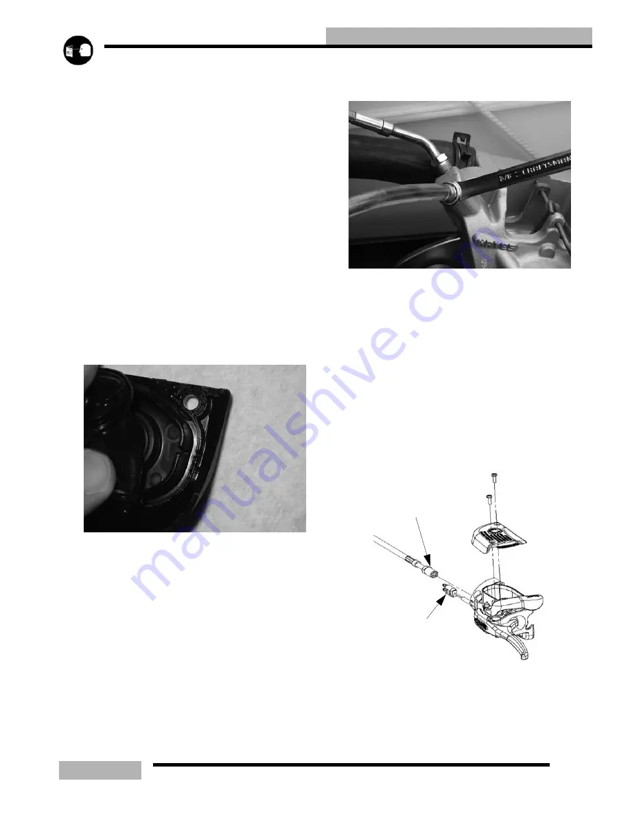
Under the cover, inspect the vent slots under the bellows
and remove any debris or blockage.
5.
Bleed or replace the fluid by attaching a clear hose from
the caliper bleeder fitting to a clean container. Be sure the
hose fits tightly on the bleeder fitting.
6.
Pump the brake lever a few times and hold.
7.
Slowly open the bleeder fitting and let the old fluid or air
escape. You will feel the lever release as you let the fluid
or air escape.
8.
Pump the brake lever a few times and hold it again.
9.
Repeat steps 7 and 8 until you see new brake fluid coming
from the caliper bleeder fitting or if you are bleeding the
air, repeat this step until you see only fluid coming out.
This may take several intervals.
10. Torque the bleeder screw to 8-11 ft-lb (11-15Nm).
11. When adding fluid, add DOT 4 brake fluid to 1/4-5/16”
(.6-.8 cm) from the reservoir top.
12. Install cover and diaphragm assembly.
13. Tighten the cover screws to 16-20 in-lb (1.8-2.3Nm).
14. Field test machine before putting into service. Check for
proper braking action and lever reserve. Lever reserve is
when the lever is firmly applied, the lever reserve should
be no less than 1/2” (1.3 cm) from the handlebar. See
“BRAKE LEVER TRAVEL” on page 3.14.
15. Verify that the sight glass indicates a full reservoir.
16. Check brake system for any fluid leaks.
BRAKE LINE REPLACEMENT
Follow these steps if the brake line is to be replaced.
1.
If needed bleed the brake system by attaching a clear hose
to the caliper bleed fitting.
144-192 in-lb (16.2-21.6Nm)
brake light switch
Содержание SUPERSPORT 2006
Страница 48: ...NOTES SPECIFICATIONS 1 48...
Страница 55: ...2 7 GENERAL SAE TAP DRILL SIZES METRIC TAP DRILL SIZES DECMIAL EQUIVALENTS...
Страница 60: ...2 12 GENERAL SPECIAL TOOLS...
Страница 61: ...2 13 GENERAL...
Страница 62: ...2 14 GENERAL...
Страница 106: ...4 18 CARBURETION...
Страница 139: ...6 27 ENGINE 340 550 ENGINE REBUILDING 10 11 3 4 12 13 5 2 14 1 16 15 16 9 17 6 7 8...
Страница 156: ...7 12 CLUTCHING 1 1 2 3 4 5 6 7 18 17 10 8 9 13 12 11 15 16 14...
Страница 192: ...8 20 FINAL DRIVE...
Страница 200: ...10 2 FRONT SUSPENSION STEERING FUSION IQ RMK 600 RMK Fusion 14 78...
Страница 201: ...10 3 FRONT SUSPENSION STEERING EDGE RMK Apply Polaris All Season Grease to all zerks...
Страница 202: ...10 4 FRONT SUSPENSION STEERING 42 5 EDGE Apply Polaris All Season Grease to all zerks...
Страница 203: ...10 5 FRONT SUSPENSION STEERING WIDETRAK Apply Polaris All Season Grease to all zerks...
Страница 244: ...11 28 REAR SUSPENSION...
Страница 256: ...12 12 CHASSIS HOOD...
Страница 282: ...13 26 ELECTRICAL...
Страница 288: ...13 32 ELECTRICAL...
Страница 289: ...14 1 WIRE DIAGRAM 2006 600 FUSION HO HOOD...
Страница 290: ...14 2 WIRE DIAGRAM 2006 HO RMK HOOD...
Страница 291: ...14 3 WIRE DIAGRAM 600 HO FUSION RMK CHASSIS...
Страница 292: ...14 4 WIRE DIAGRAM 600 HO FUSION RMK CHASSIS CALL OUTS...
Страница 293: ...14 5 WIRE DIAGRAM 700 900 ENGINE...
Страница 294: ...14 6 WIRE DIAGRAM 700 900 ENGINE AND ENGINE CALL OUTS...
Страница 295: ...14 7 WIRE DIAGRAM 700 900 CHASSIS...
Страница 297: ...14 9 WIRE DIAGRAM 340 550 FUJI FAN ENGINE CHASSIS...
Страница 298: ...14 10 WIRE DIAGRAM 500 FUJI ENGINE CHASSIS...
Страница 299: ...14 11 WIRE DIAGRAM 500 600 IBERTY ENGINE CHASSIS...
Страница 300: ...14 12 WIRE DIAGRAM WIDETRAK ENGINE CHASSIS...


