background image

95

Plasma Display Ceiling Suspension Hardware: PDK-5012

5

°

10

°

15

°

20

°

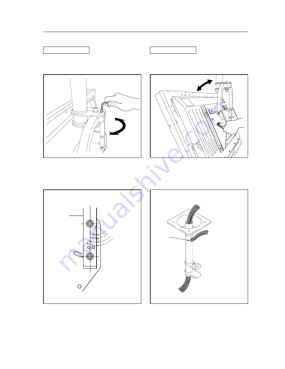
4.8.5 Angle setup

Left-right Adjustment

You can adjust it 45° to the left or right by loosening the

top screw.

Set the desired angle, then tighten the screw.

Vertical Adjustment

You can adjust its vertical angle by loosening the screws

on the left and right sides. (You can adjust it a maximum

of 25° downwards from the vertical position.)

Set it to the desired angles while supporting the plasma display and retighten the loosened screws on the left and right

sides. The hole on the side indicates the angle. (5° units).

Detailed Angle Standard Diagram

Connecting cable

(when coming out of the top

of the supporting column)

Connecting cable

(when coming out of

the hole)

To the connector on the plasma display

Hole

[503CMX/503MXE : 433CMX/433MXE]

Содержание PDP 503CMX

Страница 1: ...rom modifications made to this product or from natural disasters PRECAUTIONS We accept no responsibility for losses resulting from the use of parts other than those supplied by us We guarantee the performance of our products only when they are assembled and adjusted as described in this manual The specifications and external designs shown in this manual are subject to change without notice CAUTION...

Страница 2: ...o stabilize the stand to the floor 75 4 5 3 External Dimensions 75 4 5 4 Stand assembling 76 4 5 5 Stand attaching to the Plasma Display 76 Table of Contents 4 6 Wall Mounted Tiltable Plasma Display Hardware PDK 5011 80 4 6 1 Specifications 80 4 6 2 External Dimensions 81 4 6 3 Assembling the mounting hardware and mounting the plasma display 82 4 6 4 Angle setup 84 4 6 5 Measure to prevent shakine...

Страница 3: ...ustments and settings in integrator mode 151 1 Adjusting PICTURE picture quality 151 2 Adjusting WHITE BALANCE 152 3 Adjusting SCREEN screen position 152 4 Setting the 4 screen display 2x2 mode 153 5 Setting brightness enhancement at screen center 154 6 Setting the HDTV MODE 155 7 Setting component input 156 8 Adjusting SUB VOLUME 157 9 Setting the OSD display 159 10 Setting the baud rate 160 11 S...

Страница 4: ...en the PAD 5002 is not installed the PDP 503CMX PDP 503MXE will not handle the following functions Input terminals INPUT 1 2 Input Component video signal RGB signals from AV devices other than PCs INPUT 3 Input S terminal mini DIN 4 PIN connector Y C separate video signal Input Pin jacks x 2 Audio L R signal INPUT 4 Input BNC terminal Composite video signal Output BNC terminal Input Pin jack x 2 A...

Страница 5: ...e power control function provides a 20 reductioninpowerconsumptioncomparedtonormaloperating conditions MODE 1 with color bar signal input Features and Functions of this device PDP 433CMX PDP 433MXE Introduces newly developed 43 high precision Wide Plasma Panel The new high precision 43 wide plasma panel 1 024 by 768 dots 16 9 pushes the envelope of previous high luminance panels producingbrighter ...

Страница 6: ...ack x2 for INPUT 3 L R 500mVrms more than 10 kΩ AUDIO INPUT Input Pin jack x2 for INPUT 4 L R 500mVrms more than 10 kΩ Control related RS 232C terminal D sub 9 pin male NOTE 1 Combination In Out Terminal Mini DIN 6 pin Control In Out Terminal Monaural mini jack 2 Power requirements PDP 503CMX AC 100 V to 120 V 50 60 Hz PDP 503MXE AC 100 V to 240 V 50 60 Hz In rush less than 30 A Power factor more ...

Страница 7: ...rms more than 10 kΩ AUDIO INPUT Input Pin jack x2 for INPUT 4 L R 500mVrms more than 10 kΩ Control related RS 232C terminal D sub 9 pin male NOTE 1 Combination In Out Terminal Mini DIN 6 pin Control In Out Terminal Monaural mini jack 2 Power requirements PDP 433CMX AC 100 V to 120 V 50 60 Hz PDP 433MXE AC 100 V to 240 V 50 60 Hz In rush less than 30 A Power factor more than 0 95 Consumption PDP 43...

Страница 8: ...60Hz 66 7Hz 72Hz 75Hz 85Hz 56Hz 60Hz 72Hz 75Hz 85Hz 640 x 400 640 x 480 800 x 600 NEC PC 9800 NEC PC 9800 852 x 480 864 x 480 Apple Macintosh 13 1072 x 600 24 8kHz 31 5kHz 31 5kHz 35 0kHz 37 9kHz 37 5kHz 43 3kHz 35 2kHz 37 9kHz 48 1kHz 46 9kHz 53 7kHz Remark Resolution Dot x Line Vertical Frequency Horizontal Frequency 56Hz 60Hz 70Hz 60Hz 45 1kHz 48 4kHz 55 5kHz 60 0kHz 1280 x 768 1280 x 960 1280 ...

Страница 9: ...ignal NTSC PAL SECAM 4 43 NTSC INPUT 5 applies only when equipped with PDA 5002 PC signals supported 60Hz 56Hz 60Hz 60Hz 60Hz 60Hz 56Hz 60Hz 60Hz 60Hz 640 x 480 800 x 600 852 x 480 1024 x 768 1152 x 864 1280 x 768 1280 x 960 1280 x 1024 31 5kHz 35 1kHz 37 9kHz 31 7kHz 48 4kHz 53 7kHz 45 1kHz 48 1kHz 60 0kHz 64 0kHz Remark Resolution Dot x Line Vertical Frequency Horizontal Frequency ...

Страница 10: ...ioneer original colors For packaging information refer to 3 4 2 Unpacking Center of gravity Unit mm External Dimensions PDP 503CMX PDP 503MXE 45 1218 609 714 628 620 5 effective screen dimensions 1261 4 1098 2 effective screen dimensions 1111 Light sensor for the remote 340 Unit operating panel 98 65 MAIN POWER switch 950 centering Terminal area dimensions Rear View 1162 590 496 104 104 150 150 25...

Страница 11: ...ioneer original colors For packaging information refer to 3 4 2 Unpacking Center of gravity Unit mm External Dimensions PDP 433CMX PDP 433MXE Rear View 1014 45 535 1070 630 544 536 1 effective screen dimensions 1092 8 305 952 3 effective screen dimensions 963 Light sensor for the remote 98 65 MAIN POWER switch 910 centering Terminal area dimensions 150 150 14 M8 496 628 70 70 288 208 208 Unit oper...

Страница 12: ...12 Main Unit Operation Panel Light Sensor for the Remote External Dimensions INPUT MENU ADJUST SET SCREENSIZE AUTOSETUP STANDBY ON 22 5 14 85 5 105 39 ø15 2 ...

Страница 13: ...utton This switches between main unit panel and remote control operation permitted forbidden 6 INPUT button Press to select input 7 MENU button Press to open and close the on screen menu 8 ADJUST 5 3 2 buttons Use to navigate menu screens and to adjust various settings on the unit Usage of cursor buttons within operations is clearly indicated in the on screen display 9 SET button Press to adjust o...

Страница 14: ...able on the market as the connecting cable NOTE It has no ABL linking function And it is not compatible with the RM V4000V or other multi projection It is not output when the main power is off 4 RS 232C This terminal is used for adjustments by a PC EIA 232 F standard See 5 5 RS 232C Adjustment Mode 5 INPUT1 mini D sub 15 pin For connection of components that have RGB or component applies only when...

Страница 15: ...er cable to this connector and the other end to a standard AC power source SPEAKER L terminal For connection of an external left speaker Connect a speaker that has an impedance of 8 16 Ω Video Card PDA 5002 Section applies only when equipped with PDA 5002 INPUT5 DVI D jack Use to connect a computer Note This unit does not support the display of copyguard protected video signals AUDIO INPUT3 RCA Pi...

Страница 16: ...als INPUT1 output terminals 1 R or CR PR 2 G or Y 3 B or CB PB 4 NC not connected 5 GND 6 GND 7 GND 8 GND 9 DDC 5V NC not connected 10 GND 11 NC not connected 12 DDC SDA NC not connected 13 HD or H V SYNC 14 VD 15 DDC SCL NC not connected 1 6 11 15 5 10 INPUT 5 applies only when equipped with PDA 5002 DVI D 24 pin connector female pin layout Signal Assignment 1 2 3 4 5 6 7 8 9 10 11 12 13 14 15 16...

Страница 17: ...ons within operations is clearly indicated at the bottom the on screen menu display 5 SET button Press to adjust or enter various settings on the unit 6 MUTING button Press to mute the volume 7 AUTO SET UP button When entering a computer signal to INPUT 1 or 2 automatically sets the POSITION and CLOCK PHASE to optimum values 8 STANDBY ON button Press to put the unit in operation or standby mode 9 ...

Страница 18: ...rface so that it will be available for putting away the remote control unit when it is not in use NOTE Do not obstruct the ventilation holes in the remote control unit holder Example of remote control unit holder attachment Area of remote control unit holder attachment Remote control unit holder Remote control unit Upper and lower tape On the PDP 433CMX PDP 433MXE the remote control unit holder ca...

Страница 19: ...19 Remote Control Unit Holder ...

Страница 20: ...llation work The installation work should be conducted by two or more persons 5 Nearby equipment If air conditioning ducts or lamps etc are located near the installation site the attendant dust extreme temperatures humidity and condensation may become sources of trouble Please take sufficient steps to avoid this 6 Safe locations Do not install the unit where it may be easily touched or leaned agai...

Страница 21: ...er unit PDP 503CMX PDP 503MXE 400 W 400 VA PDP 433CMX PDP 433MXE 320 W 320 VA NOTE The in rush current upon powering will be approximately 30 A A grounded three core power cable is used by the plasma display in order to maintain its functions Connect the power cord by inserting it in a grounded electrical outlet making sure that the cord is properly grounded When using a power source use conversio...

Страница 22: ...ese openings Unit mm 500 80 154 154 80 59 72 14 5 59 357 5 211 134 5 65 82 40 82 40 166 5 138 176 164 140 165 425 165 166 5 134 5 65 58 65 172 5 72 59 357 5 211 A Fan 2 in number Two fans and part A in a normal installation case draw off hot air from the unit All openings not assisted by fans serve as air inlets If the unit is hung from or embedded into a wall special operating temperature limits ...

Страница 23: ...s are shown below Installation Conditions Always use a minimum of 4 mounting holes evenly distributed on opposite sides of both the horizontal and vertical center lines Use bolts that can be driven 12 to 18 mm into holes a or b as shown in the Side View above Do not block or cover air outlets and openings for ventilation on the rear panel Take precautions to prevent soiling walls behind the produc...

Страница 24: ... of the horizontal and vertical center lines as shown in the illustration below Do not secure the unit at four points arranged in a single row as shown below Methods for securing Unfavorable examples Methods for securing Favorable examples A Secured at eight points B Secured at six points C Secured at four points with mounting hardware attached to the sides 503CMX 503MXE ...

Страница 25: ...the warp of the mount surface is less than 1mm 1 Referring to the illustration below diagonally extend string of maximum φ 0 1 mm diameter through the bolt mount openings Strings thus arranged should be completely free of slack 2 Measure the clearance L between the strings at their point of intersection Distortion is expressed by Distortion L 2 3 If L is found to be 0 pass the strings through the ...

Страница 26: ...gs Unit mm 288 5 40 5 40 5 185 192 5 33 5 58 5 65 59 14 5 405 35 142 5 35 142 5 125 132 5 88 142 142 88 125 33 5 58 5 132 5 185 192 5 66 133 5 79 45 57 5 511 66 79 133 5 Fan 2 in number A Two fans and part A in a normal installation case draw off hot air from the unit All openings not assisted by fans serve as air inlets If the unit is hung from or embedded into a wall special operating temperatur...

Страница 27: ...ount holes are shown below Installation Conditions Always use a minimum of 4 mounting holes evenly distributed on opposite sides of both the horizontal and vertical center lines Use bolts that can be driven 12 to 18 mm into holes a or b as shown in the Side View above Do not block or cover air outlets and openings for ventilation on the rear panel Take precautions to prevent soiling walls behind t...

Страница 28: ... illustration below Do not secure the unit at four points arranged in a single row as shown below Methods for securing Unfavorable examples Methods for securing Favorable examples A Secured at six points B Secured at four points with mounting hardware attached to the sides 433CMX 433MXE C Secured at four points with mounting hardware attached horizontally Take proper precautions to prevent pinchin...

Страница 29: ...ration below diagonally extend string of maximum φ 0 1 mm diameter through the bolt mount openings Strings thus arranged should be completely free of slack 2 Measure the clearance L between the strings at their point of intersection Distortion is expressed by Distortion L 2 3 If L is found to be 0 pass the strings through the other bolt mount openings and repeat the measurements Any value of L gre...

Страница 30: ...from being dameged 3 4 2 Unpacking The original packing material can be re used to sofely ship the Plasma Display When doing so it is important to use the material in the same way as when they were originally shipped Failure to correctly use the material can damage the display 1 Packing specifications PDP 503CMX PDP 503MXE 1341 W 846 H 424 D 51 kg PDP 433CMX PDP 433MXE 1193 W 748 H 424 D 41 5 kg 1...

Страница 31: ...y after all work and preparations for the installation site including clean up following unpacking are complete 3 4 3 Mounting on the attachment stands See 4 3 Installation of the Attachment Stand for in structions on permanent installation Insert the stand bolts into A and A or into B and B on the back of the main unit This method should insofar as possible be a temporary setup pending proper ins...

Страница 32: ...ents above 2 Connecting signal cables 1 Please refer to p10 14 of the instruction manual for instructions on how to connect a PC or a video device 2 Important notes Use coaxial cables As a rough guide for video signals use 3C 2V cables for lengths up to 15 meters and 5C 2V cables for lengths up to 30 meters Use thicker cables for computer signals since these signals are more likely to degrade 5C 2...

Страница 33: ... to fix the clamp Speed clamps are designed to be difficult to undo once in place Please attach carefully To attach the speed clamps to the main unit Connect the speed clamps using the 4 holes marked with below depending on the situation To remove speed clamps Using pliers twist the clamp 90 and pull it outward In some cases the clamp may have deteriorated over time and may be damaged when removed...

Страница 34: ...Never block or cover openings aside from those shown as blocked in the illustrations on the following page 4 The fittings should have a thickness of less than 20 mm This limit does not apply to fittings in examples 2 4 6 and 8 on the following page 5 L shaped fittings should have a thickness of less than 100 mm 6 The strength of the fittings should be adequate to bear the weight of the display 7 T...

Страница 35: ... left side viewed from the rear Example 1 Example 2 Example 3 Example 4 35 mm or less Example 5 Example 6 35 mm or less Example 7 Example 8 35 mm or less Vertical installation Standard installation Note that only Examples 2 and 3 apply in cases where top and bottom are reversed 503CMX 503MXE ...

Страница 36: ... unit and the wall must be no less than 50 mm Distance from wall A B C D Ambient temperature 50 mm or less 300 mm or more 300 mm or more 300 mm or more 0 to 35 C 50 mm or more 100 mm or more 50 mm or more 50 mm or more 0 to 40 C Horizontal vertical left right reverse installation Note that only Examples 2 and 3 apply in cases where top and bottom are reversed No matter what the distance between th...

Страница 37: ...equirements Free air flow With no obstructions within a distance of 300 mm from the unit Temperature of 0 35 C Flush wall installation distance between unit and wall less than 50 mm 300 mm or more 100 mm or more 50 mm or more Panting net 300 mm or more 50 mm or more 50 mm or more Requirements Free air flow With no obstructions within a distance of 300 mm from the unit around all four sides of the ...

Страница 38: ...ng to embed the unit in a wall and make sure to observe all the limitations specified below Be sure to mount the unit so that twisting bending or other deformation of the unit does not exceed 4 mm 1 Embedding in walls with space provided behind the unit With no obstructions within a distance of 300 mm from the back surface of the unit A Methods of Securing Basic methods of securing are shown below...

Страница 39: ...stration for reference purposes Make measurements at a distance of 5 cm from the unit without directly subjecting the thermometer to fan exhaust For spaces where temperature fluctuations are likely gather additional measurement points for an adequate data set 50mm 50mm 503CMX 503MXE ...

Страница 40: ...nstallation Embedding in the wall 2 Embedding in walls with no space provided behind the unit Panting Punching net numerical aperture 50 or over 100mm or more 100mm or more 100mm or more 100mm or more 50mm or more 503CMX 503MXE Methods of Securing Basic methods of securing are shown below Avoid blocking or covering areas aside from those indicated by The methods indicated by a large X mark must no...

Страница 41: ...rature range If hot air remains in the closed space the temperature may rise causing a malfunction or fire As a precaution in case of accidents the inner wall should have sufficient heat resistance or fire resistance Usage temperature conditions BOX air temperature Ambient temperature 0 to 35 C A A B B C D B 30 mm B 50 mm A 50 mm 1118 mm or more A 50 mm 1118 mm or more Mesh with aperture efficienc...

Страница 42: ...ht of the support brackets 3 5 5 Ceiling suspension with wires When suspending from ceilings with wire attach the unit either at rows A and B or at rows C and D to keep it from deforming forces In addition the unit must be attached at four or more points with these points distributed symmetrically on opposite sides of the vertical and horizontal center lines Operating Temperature Restrictions Ambi...

Страница 43: ...ocking or covering areas aside from those indicated by The methods indicated by a large X mark must not be used Before attaching the unit to fittings double check that the thickness and height of the fittings and the number of fixing bolts is correct Also refer to 3 5 1 Mounting to fittings Vertical suspension 503CMX 503MXE ...

Страница 44: ...tions specified below Be sure to mount the unit so that twisting bending or any other deformation does not exceed 4 mm Shaded areas indicate attachment points for mounting hardware Operating Temperature Restrictions Distance from wall A B C D Ambient temperature 50 mm or more 100 mm or more 50 mm or more 50 mm or more 0 to 40 C Avoid blocking or covering this area on the upper and lower sides Atta...

Страница 45: ...double check that the thickness and height of the fittings and the number of fixing bolts is correct Also refer to 3 5 1 Mounting to fittings NOTE 1 Heated air is drawn off from the interior of the unit by fans Before installation consider the heat resistance of the wall or other surfaces behind the unit Exhaust temperatures can be 30 C higher than the outside temperature NOTE 2 For wall mounting ...

Страница 46: ... 7 Place product upright and flush into wall embedding in the wall Carefully read the following before trying to embed the unit in a wall and make sure to observe all the limitations specified below Be sure to mount the unit so that twisting bending or other deformation of the unit does not exceed 4 mm 1 Embedding in walls with space provided behind the unit with no obstructions within a distance ...

Страница 47: ...ng are shown below Avoid blocking or covering areas aside from those indicated by The methods indicated by a large X mark must not be used Before attaching the unit to fittings double check that the thickness and height of the fittings and the number of fixing bolts is correct Also refer to 3 5 1 Mounting to fittings 503CMX 503MXE ...

Страница 48: ...t temperature 0 to 35 C Special Installation Place product upright and flush into wall embedding in the wall 2 Embedding in walls with no space provided behind the unit Panting Punching net numerical aperture 50 or over 100mm or more 100mm or more 100mm or more 100mm or more 50mm or more Attach this fan on the left side 503CMX 503MXE ...

Страница 49: ...ng are shown below Avoid blocking or covering areas aside from those indicated by The methods indicated by a large X mark must not be used Before attaching the unit to fittings double check that the thickness and height of the fittings and the number of fixing bolts is correct Also refer to 3 5 1 Mounting to fittings 503CMX 503MXE ...

Страница 50: ...ons While the display is designed to accommodate side by side installations keep in mind that specific installation configurations may affect ventilation Observe the following requirements 1 Installation of up to two units Horizontal connection The following table lists the operating temperature conditions Use the units under conditions that keep the outside atmosphere in this range Special instal...

Страница 51: ...re conditions Use the units under conditions that keep the outside atmosphere in this range Special installation Multiple A Unit A Unit B Unit B Partition In case of lateral connections ensure that left and right partitions are provided Be careful to install the partitions so that the air on the left and right backside of the set is not mixed up Operating Temperature Restrictions Distance from wal...

Страница 52: ...Never block or cover openings aside from those shown as blocked in the illustrations on the following page 4 The fittings should have a thickness of less than 20 mm This limit does not apply to fittings in examples 1 3 5 and 6 on the following page 5 L shaped fittings should have a thickness of less than 100 mm 6 The strength of the fittings should be adequate to bear the weight of the display 7 T...

Страница 53: ...o that the fan is on the left side viewed from the rear Example 1 Example 2 Example 3 Example 4 Example 5 35 mm or less Example 6 Vertical installation Standard installation Note that only Examples 1 and 2 apply in cases where top and bottom are reversed 433CMX 433MXE ...

Страница 54: ...all A B C D Ambient temperature 50 mm or less 300 mm or more 300 mm or more 300 mm or more 0 to 35 C 50 mm or more 100 mm or more 50 mm or more 50 mm or more 0 to 40 C Horizontal vertical left right reverse installation Note that only Examples 2 and 3 apply in cases where top and bottom are reversed No matter what the distance between the unit and the wall the unit must be installed in such a way ...

Страница 55: ...th no obstructions within a distance of 300 mm from the unit Temperature of 0 35 C Flush wall installation distance between unit and wall less than 50 mm 300 mm or more 100 mm or more 50 mm or more Panting net 300 mm or more 50 mm or more 50 mm or more Requirements Free air flow With no obstructions within a distance of 300 mm from the unit around all four sides of the unit is not necessarily requ...

Страница 56: ...ead the following before trying to embed the unit in a wall and make sure to observe all the limitations specified below Be sure to mount the unit so that twisting bending or other deformation of the unit does not exceed 4 mm 1 Embedding in walls with space provided behind the unit With no obstructions within a distance of 300 mm from the back surface of the unit A Methods of Securing Basic method...

Страница 57: ...stration for reference purposes Make measurements at a distance of 5 cm from the unit without directly subjecting the thermometer to fan exhaust For spaces where temperature fluctuations are likely gather additional measurement points for an adequate data set 50mm 50mm 433CMX 433MXE ...

Страница 58: ...nstallation Embedding in the wall 2 Embedding in walls with no space provided behind the unit Panting Punching net numerical aperture 50 or over 100mm or more 100mm or more 100mm or more 100mm or more 50mm or more 433CMX 433MXE Methods of Securing Basic methods of securing are shown below Avoid blocking or covering areas aside from those indicated by The methods indicated by a large X mark must no...

Страница 59: ...erature range If hot air remains in the closed space the temperature may rise causing a malfunction or fire As a precaution in case of accidents the inner wall should have sufficient heat resistance or fire resistance Usage temperature conditions BOX air temperature Ambient temperature 0 to 35 C A A B B C D B 30 mm B 50 mm A 50 mm 800 mm or more A 50 mm 800 mm or more Mesh with aperture efficiency...

Страница 60: ...ight of the support brackets 3 6 5 Ceiling suspension with wires When suspending from ceilings with wire attach the unit either at rows A and B or at rows C and D to keep it from deforming forces In addition the unit must be attached at four or more points with these points distributed symmetrically on opposite sides of the vertical and horizontal center lines Operating Temperature Restrictions Am...

Страница 61: ...ocking or covering areas aside from those indicated by The methods indicated by a large X mark must not be used Before attaching the unit to fittings double check that the thickness and height of the fittings and the number of fixing bolts is correct Also refer to 3 6 1 Mounting to fittings Vertical suspension 433CMX 433MXE ...

Страница 62: ...itations specified below Be sure to mount the unit so that twisting bending or any other deformation does not exceed 4 mm Shaded areas indicate attachment points for mounting hardware Operating Temperature Restrictions Distance from wall A B C D Ambient temperature 50 mm or more 100 mm or more 50 mm or more 50 mm or more 0 to 40 C Avoid blocking or covering this area on the upper and lower sides A...

Страница 63: ...double check that the thickness and height of the fittings and the number of fixing bolts is correct Also refer to 3 6 1 Mounting to fittings NOTE 1 Heated air is drawn off from the interior of the unit by fans Before installation consider the heat resistance of the wall or other surfaces behind the unit Exhaust temperatures can be 30 C higher than the outside temperature NOTE 2 For wall mounting ...

Страница 64: ...n of the unit does not exceed 4 mm 1 Embedding in walls with space provided behind the unit with no obstructions within a distance of 300mm from the back surface of the unit A A A A 433CMX 433MXE Operating Temperature Restrictions Temperature in space X and Y A 0 to 370 mm 0 to 40 C Methods of Securing Basic methods of securing are shown below Avoid blocking or covering areas aside from those indi...

Страница 65: ...hing net numerical aperture 50 or over 100mm or more 100mm or more 100mm or more 100mm or more 50mm or more Attach this fan on the left side 433CMX 433MXE Methods of Securing Basic methods of securing are shown below Avoid blocking or covering areas aside from those indicated by The methods indicated by a large X mark must not be used Before attaching the unit to fittings double check that the thi...

Страница 66: ...ons While the display is designed to accommodate side by side installations keep in mind that specific installation configurations may affect ventilation Observe the following requirements 1 Installation of up to two units Horizontal connection The following table lists the operating temperature conditions Use the units under conditions that keep the outside atmosphere in this range Special instal...

Страница 67: ...re conditions Use the units under conditions that keep the outside atmosphere in this range Special installation Multiple A Unit A Unit B Unit B Partition In case of lateral connections ensure that left and right partitions are provided Be careful to install the partitions so that the air on the left and right backside of the set is not mixed up Operating Temperature Restrictions Distance from wal...

Страница 68: ...l is 32 mm It is provided with many installation holes for various hypothetical walls and it is constructed so that it can be easily attached to the main unit Plasma Display Ceiling Suspension Hardware PDK 5012 Simple rod type mounting hardware permitting display panning over a range of 45 degrees and up to 25 degree downward tilting from the horizontal This hardware enables installation of the un...

Страница 69: ...rticulars of an installation are letter perfect your work may be perceived as inadequate unless you patiently and thoroughly explain these precautions so that the customer fully understands them The following are highly dangerous and must be avoided at all times Any sudden application of force including pushing and pulling Splashing water on the unit Placing any object on the unit Touching mount s...

Страница 70: ... of the platform 1 PDP 503CMX PDP 503MXE 2 PDP 433CMX PDP 433MXE 2 Insert the unit into the stand 3 Tighten the bolt against the washer so as to secure the unit The unit weights 30 kg or more and its thinness makes it unstable Therefore it should be unpacked carried and installed by two or more persons CAUTION Front Rear 798mm 1 768mm 2 110 Use a 6 mm hexagonal wrench to tighten the bolt 503CMX 50...

Страница 71: ...d Dimensions Unit mm Dimensions in are the dimensiions for the PDP 433CMX PDP 433MXE 31 4 314 149 65 127 7 98 74 3 300 737 630 714 607 23 1218 1070 300 728 698 70 110 66 8 ø24 R12 70 53 5 10 24 3 10 22 1 10 10 50 503CMX 503MXE 433CMX 433MXE ...

Страница 72: ...lbs Input Output Video INPUT3 Input S terminal MiniDIN 4 pin INPUT4 Input BNC jack Composite video signal 1 Vp p 75Ω negative sync Output BNC jack 75Ω with buffer INPUT5 Input Digital RGB DVI D24 pin Audio INPUT3 Input Pin jack 2 L R 500 mVrms more than 10 kΩ INPUT4 Input Pin jack 2 L R 500 mVrms more than 10 kΩ Accessories Label for remote control unit 1 BNC Pin conversion adaptor 1 Connector ind...

Страница 73: ...n any way Before installation take precautions to eliminate static electricity on your body Do not touch the card s circuitry or devices This device has not been designed to allow reinstallation or removal after the card has once been installed on the plasma display do not attempt to remove it since damage may result Installation 1 Remove the protective cover over the video card slot on the plasma...

Страница 74: ...l color Stand pipes semi matt black paint Package dimensions 640 W 214 H 415 D mm 25 3 16 W 8 7 16 H 16 11 32 D in Package weight 6 3 kg 13 9 lbs Accessories Base cover 1 Stand pipes left and right interchangeable 2 Screw 4 8 4 Installation bolt 1 M8 20 2 Installation bolt 2 M8 40 2 Hexagonal wrench 1 Stabilization bolts 2 Operating instructions 1 Tabletop Stand PDK TS01 Operating Temperature Rest...

Страница 75: ...the stand to the floor use M6 with a length above 20 mm Unit mm Tabletop Stand PDK TS01 4 5 3 External Dimensions 7 When using plasma display monitor PDP 503CMX or PDP 503MXE Unit mm 503CMX 503MXE 433CMX 433MXE 566 11 5 R6400 R4200 R6400 550 774 150 220 339 508 566 1218 7 When using plasma display monitor PDP 433CMX or PDP 433MXE Unit mm 1070 566 220 150 685 508 339 ...

Страница 76: ...own the bolt when the threads are no longer visible Holes a Plasma display housing 4 5 5 Stand attaching to the Plasma Display 1 Normal Installation 1 With the plasma display lying flat insert and secure the two Installation bolts 1 M8 20 in the holes a located in the plasma display housing At this point tighten these bolts 1 only until the threads are no longer visible when viewed from t he side ...

Страница 77: ...ass the installation bolts 2 M8 40 through the stand pipes and tighten the installation bolts securely with the included hexagonal wrench holes should be used in the proper B B 4 Tighten the installation bolts 1 securely with the hexagonal wrench provided 1 Place a sheet or protective cover to protect the display from scratches or damage 2 Assemble only with the plasma display lying flat on a tabl...

Страница 78: ...ay Mirror mat Pads Inner box frame Plasma display Mirror mat Inner box frame topped by two pads Pad 1 Construct the stand for the plasma display using the inner box frame and pads shown in the figure above 2 Set the plasma display down on the pads as shown in the figure below 3 Follow the instructions in Steps 1 4 in Normal Installation to attach the stand to the plasma display 503CMX 503MXE 433CM...

Страница 79: ...tabilize the display by connecting to a wall or standing beam with a strong cord Repeat the same steps in the laterally direction to stabilize the assembly to the left and right Use cord and hooks that are available on the market sold separately 7 How to use the stabilization bolts 7 Stabilizing to the floor Use screws sold separately to attach and stabilize the stand The panel shown is PDP 503CMX...

Страница 80: ... General structural steel tubes STK MR Finish Semi matte black paint on rear Original Pioneer color Dimensions of packaging 890 W 120 H 700 D mm 35 1 32 W 4 23 32 H 27 9 16 D in Package weight 18 0 kg 39 7 lbs Layers of packing 20 layers Components Hung on wall unit 1 Bolt M8 6 Hexagonal wrench 1 In wall mounting installation allow adequate space a clearance of 300 mm or more above and below the m...

Страница 81: ...sma display monitor PDP 503CMX or PDP 503MXE Units mm 6 φ10 5 6 23X10 5 98 33 35 150 150 35 35 714 44 455 555 655 496 740 1218 545 465 232 212 410 143 45 44 573 258 54 43 125 25 C L center of the display 503CMX 503MXE 433CMX 433MXE 7 When using plasma display monitor PDP 433CMX or PDP 433MXE Units mm ...

Страница 82: ... sheet or similar protective material to protect it from scratches or other dam age Be sure to attach it on top of a flat table or similar surface 4 Fix the plasma display to the PDP side hardware with bolt M8 6 locations Usually use the holes marked with the red triangle If the 43 inch model is installed with an inclination of 18 or more the top part of the screw used to adjust the angle may be v...

Страница 83: ...p 1 one on the left and one on the right Special screw M6 Wall mounted tiltable plasma display hardware PDK 5011 Hook 6 Attach the hook on the PDP side hardware to the wall side hardware Warning Do not hold the speakers during the installation work 503CMX 503MXE 433CMX 433MXE ...

Страница 84: ... at any angle from the vertical to 25 This adjustment must always be done by 2 people Adjust the angle by rotating the screws at the center top and center bottom of the wall side hardware to the left or right Warning If the angle is increased while you are adjusting the angle using the screw at the center of the bottom it is difficult to turn the screw When this happens adjust it at the center of ...

Страница 85: ...r to loosen left right the installation screws on the resin plate used as a guideline when installing it vertically left right so that the resin plate can move freely 2 Slide the resin plate left right forward along the slit to the rear cover of the plasma display 3 If when it is moved only forward the distance is too short rotate the resin plate to use the long side direction 4 After setting the ...

Страница 86: ...r Original Pioneer color Dimensions of packaging 1070 W 90 H 590 D mm 42 1 8 W 3 17 32 H 23 7 32 D in Package weight 12 0 kg 26 5 lbs Layers of packing 30 layers Components Hung on wall unit 1 Bolt M8 6 Hexagonal wrench Opposite side 6 mm for M8 use 1 Stencil 1 In wall mounting installation allow adequate space a clearance of 300 mm or more above and below the monitor set as well as on the right a...

Страница 87: ...714 1218 98 32 396 15 940 496 455 496 540 120 120 225 150 150 27 135 45 135 45 94 5 682 5 425 60 2 φ C L Center of the display 503CMX 503MXE 433CMX 433MXE 7 When using plasma display monitor PDP 433CMX or PDP 433MXE Unit mm 17 6x120 6 6x63 Center line Center of the display 98 1070 425 682 5 94 5 45 135 45 135 27 150 150 225 120 120 540 496 455 400 940 15 396 32 630 910 65 65 115 90 2 φ60 ...

Страница 88: ... with a sheet or similar protective material to protect it from scratches or other damage Be sure to attach it on top of a flat table or similar surface 4 Fix the plasma display to the PDP side hardware with bolt M8 6 locations PDP side hardware Plasma display Top side of plasma display Top side of plasma display Pin 1 Remove the screws 2 locations from the bottom of the hung on wall unit with a P...

Страница 89: ... more locations symmetrically on the left and right side Because the screws and bolts used to do this are different according to the wall strength and wall material purchase suitable screws and bolts separately Warning Check the strength of the wall and beams before installing the display Hook 503CMX 503MXE 433CMX 433MXE 6 Attach the hook on the PDP side hardware to the wall side hardware While it...

Страница 90: ...r general structure STK MR Finish Semi matte black paint Original Pioneer color Package dimensions 1035 W 360 H 540 D mm 40 3 4 W 14 3 16 H 21 1 4 D in Package weight 23 5 kg 51 8 lbs Layers of packing 10 layers Components PDP bracket 1 Bolt M8 6 Special screw 4 Stencil printed on the wrapping material that is inside 1 Installer s contact information Japan only 1 Operating instructions 1 The appro...

Страница 91: ...φ240 5 216 6 1 5 R 672 R 45 45 φ60 5 329 100 714 This circle shows the path that the outermost part of the plasma display follows when it is rotated about a vertical axis after having been titled sideways by 25 This circle shows the path that the outermost part of the plasma display follows when it is rotated about a vertical axis after having been titled sideways by 25 503CMX 503MXE 433CMX 433MXE...

Страница 92: ...530 300 R605 R537 45 45 630 φ60 5 This circle shows the path that the outermost part of the plasma display follows when it is rotated about a vertical axis after having been titled sideways by 25 This circle shows the path that the outermost part of the plasma display follows when it is rotated about a vertical axis after having been titled sideways by 25 503CMX 503MXE 433CMX 433MXE Attachment use...

Страница 93: ...M6 bolts Hexagonal wrench subtense 6 mm for M8 bolts You ll also need tools for ceiling work 2 Installing the mounting hardware Select the installation site then apply the supplied pattern to the ceiling drill the holes and mount the ceiling suspension hardware The appropriate types of screws and other display mounting hardware will depend on the strength and composition of the particular ceiling ...

Страница 94: ...e is that used with the PDP 503CMX PDP503MXE PDP bracket Top side of plasma display Hanger Plasma display Hexagonal bolts Top side of plasma displa 2 Fix the plasma display to the PDP bracket with screws 6 locations Warning Be sure to use the holes hole positions on the dia gram shown on 50 to attach the PDP 503CMX or PDP 503MXE Be sure to use the holes shown on 43 to attach the PDP 433CMX PDP 433...

Страница 95: ...ews on the left and right sides You can adjust it a maximum of 25 downwards from the vertical position Set it to the desired angles while supporting the plasma display and retighten the loosened screws on the left and right sides The hole on the side indicates the angle 5 units Detailed Angle Standard Diagram Connecting cable when coming out of the top of the supporting column Connecting cable whe...

Страница 96: ...tallic Dimensions of packaging 1465 W 200 H 790 D mm 67 11 16 W 7 7 8 H 31 3 32 D in bracket display stand section 810 W 295 H 810 D mm 31 7 8 W 11 15 16 H 31 7 8 D in stand shelf leg section Package weight 38 kg 83 8 lbs bracket display stand section 21 kg 46 3 lbs stand shelf leg section Layers of packing 10 layers Components Display stand 1 Rear cover 1 Leg base 1 Bracket 1 Stand shelf 1 Hexago...

Страница 97: ...70 Center of the display screen when it is installed at the lower position 1350 Center of the display screen when it is installed at the upper position 770 Stand shelf installed at the highest position 730 Stand shelf installation spacing 40 mm Stand shelf installed at the lowest position Panel Stand shelf Stand shelf 4 9 2 External Dimensions 7 When using plasma display monitor PDP 503CMX or PDP ...

Страница 98: ...5 Panel 312 5 35 555 98 5 100 1084 5 180 65 128 5 30 22 406 650 60 720 730 Stand shelf installation spacing 40 mm 770 Stand shelf installed at the highest position 773 5 1350 Center of the display screen when it is installed at the upper position 1170 Center of the display screen when it is installed at the lower position 1518 5 1314 1070 1665 132 3 75 143 3 110 180 330 Stand shelf installed at th...

Страница 99: ...ther with more than two persons 1 Assemble the unit Attach the leg base to the display stand using the hexagonal bored bolts M8 60 so that the rear label faces towards the back casters as the figure Note In order to ensure safe installation always be sure to alternately tighten each bolt two times or more until they are firmly fixed in place Mobile Cart PDK 5014 Screws Screws Bracket Rear cover Lo...

Страница 100: ...below 3 Attaching bracket to plasma display Using the hexagonal bored bolts M8 20 attach the bracket to the rear of the plasma display by screwing the bolts into the screw holes as the figure Note 1 The plasma display should be placed on a blanket or other soft surface so as to avoid scratching or otherwise damaging the surface of the display Note 2 In order to ensure safe installation always be s...

Страница 101: ... screwing in the bolts into the screw holes located at the bottom of the protruding part of the bracket and the screw holes of the display stand 3 Screw the bolts of the protruding portion of the bracket firmly into place Note In order to ensure safe installation always be sure to alternately tighten each bolt two times or more until they are firmly fixed in place 5 Attaching the stand shelf to th...

Страница 102: ...floor 2 Turn the nut at the top of the caster in the direction indicated by the arrow to fix the caster into place 7 Hang the cords on the hooks on the back of the support columns 8 Attach the rear cover Attach the rear cover and fix it in place by tightening the finger screws Be careful not to catch the cable in the rear cover Mobile Cart PDK 5014 Bottom of support caster Support caster nut Hook ...

Страница 103: ...103 Mobile Cart PDK 5014 503CMX 503MXE 433CMX 433MXE ...

Страница 104: ...or Package dimensions 850 W 110 H 130 D mm 33 15 32 W 4 11 32 H 5 1 8 D in Package weight 5 0 kg 11 0 lbs Accessories Vertical frame 2 Horizontal frame 2 Monitor mount bolt 4 Plus minus screw with washer M5 x 50 8 Special eye bolt M8 80 4 Spring washer nut for M8 8 Hexagonal nut for M8 8 Large flat washer for M8 8 Small washer for M8 4 Operating instructions 1 Mount contractor contract form 1 The ...

Страница 105: ...unting pitch 455 63 33 798 828 1218 8 φ 9 20 700 528 148 5 660 450 410 40 714 83 PDP Bracket PDK 5005 4 10 2 External Dimensions Units mm The mounting format is symmetrical from left to right and from top to bottom 503CMX 503MXE ...

Страница 106: ...ted locations If they are used on the plasma display itself internal damage may result c h Spring washer hexagonal nut 4 Insofar as possible insert the bolt so that the nut goes all the way to its base 1 Attach the special eye bolts together with the M8 nuts to the main unit 2 After passing the bolt through secure it with the small flat washer and nut 3 Tighten the nuts with spanners 4 For additio...

Страница 107: ...arge flat washer of each monitor mounting bolts On top of these mount the assembled PDP bracket The tightening the screws on the vertical and horizontal frames should be performed on a level table as illustrated and after the positions of the holes have been aligned Washers must be used If the number and location of washers is incorrect warping of the display unit may result 4 10 4 An example of u...

Страница 108: ...Note Refer to procedure 2 on Page 94 to install the PDP 433CMX PDP 433MXE with ceiling suspension hard ware PDK 5012 4 11 2 External Dimensions Units mm Cable Cover PDA P01 45 5 123 9 754 4 11 3 Cautions 1 This cable cover was exclusively designed for plasma displays produced by PIONEER 2 This product is important for the assembled display s external appearance The cover keeps cables organized whe...

Страница 109: ...h the cable cover First slide the cable cover onto the rear case then snap the notches onto the stems of the four clips 4 Carefully arrange the cables then snap the cable cover shut into the seven square holes at the bottom of the rear panel Cable Cover PDA P01 Plasma display Ventilation holes Clips Only four clip holes are arranged along this line Holes for attach ing the clips Plasma display Cab...

Страница 110: ... 5 cm dome type Nominal impedance 8 Ω Frequency Range 50 to 20 000 Hz Sensitivity 82 dB W at 1 m distance Permissible input Max input 12 W Rated input 4 W Crossover frequency 3 kHz Accessory parts for 2 speakers Speaker cable 2 Flat countersunk head screw 4 Hexagon socket head screw 4 Mounting tool 1 Washer M8 ø25 2 Speaker mounting fittings bottom x2 Speaker mounting fittings top right x1 Speaker...

Страница 111: ... plasma display monitor when using PDP 503CMX or PDP 503MXE Center of gravity Units mm Speaker System PDP S05 LR 33 106 15 5 53 45 340 714 101 86 1368 1218 74 503CMX 503MXE These are the dimensions of the side surface of the speaker ...

Страница 112: ...lay Then install the lower fitting on the display 2 Adjust the position so that the gap between the speaker and the display is uniform and then tighten the screws firmly Speaker System PDP S05 LR Note When the display is to be moved after speaker installation do not hold the display by the speakers Hold the bottom of the display to move it Adjust the mounting plate to about 0 5 cm below the upper ...

Страница 113: ...plifier the bass reproduction will be reduced the sound positioning will be lost and a correct stereo effect will not be obtained Speaker System PDP S05 LR 2 Connection to a stereo amplifier 1 Switch off the power of the amplifier 2 Connect the input terminals of the speaker system and the speaker output terminals of the stereo amplifier with the accessory speaker cable The polarity of the input t...

Страница 114: ...2 5 cm dome type Nominal impedance 8 Ω Frequency Range 60 to 20 000 Hz Sensitivity 82 dB W at 1 m distance Permissible input Max input 12 W Rated input 4 W Crossover frequency 3 kHz Accessory parts for 2 speakers Speaker cable 2 Flat countersunk head screw 4 Hexagon socket head screw 4 Mounting tool 1 Washer M8 ø25 2 Speaker mounting fittings bottom x2 Speaker mounting fittings top right x1 Speake...

Страница 115: ... plasma display monitor when using PDP 433CMX or PDP 433MXE Center of gravity Units mm Speaker System PDP S07 LR 433CMX 433MXE 33 106 15 5 53 45 305 630 101 86 1220 1070 74 These are the dimensions of the side surface of the speaker ...

Страница 116: ...lay Then install the lower fitting on the display 2 Adjust the position so that the gap between the speaker and the display is uniform and then tighten the screws firmly Speaker System PDP S07 LR Note When the display is to be moved after speaker installation do not hold the display by the speakers Hold the bottom of the display to move it Adjust the mounting plate to about 0 5 cm below the upper ...

Страница 117: ...plifier the bass reproduction will be reduced the sound positioning will be lost and a correct stereo effect will not be obtained Speaker System PDP S07 LR 2 Connection to a stereo amplifier 1 Switch off the power of the amplifier 2 Connect the input terminals of the speaker system and the speaker output terminals of the stereo amplifier with the accessory speaker cable The polarity of the input t...

Страница 118: ...nd operations NOTE Refer to 5 4 1 About the integrator mode 1 Normal Operating Mode Intended for video playback this mode enables the following basic operations Switching to STANDBY status POWER OFF Switching to power standby status Screen size switching Volume adjustment muting remote control only AUTO SET UP only when PC signals are input POINT ZOOM only when PC signals are input only remote con...

Страница 119: ...rating panel of the main unit then make adjustments using the remote Depending on which has transmitted the more recent command either the remote the operating panel of the main unit or the RS 232C may originate the command currently in effect Example Operation Action 1 Press the MENU button on the remote control Enters Menu mode or on the operating panel of the main unit At this time the only ava...

Страница 120: ... S Video Y C S Video Y C S Video Y C S Video Y C 4 3 FULL ZOOM WIDE Remark Screen size NTSC PAL SECAM 4 43 NTSC Signal Format 50 Component RGB Component RGB Component RGB Component RGB Component RGB Component RGB Component RGB Component RGB Horizontal Frequency Fh kHz Remark 15 625 28 1 31 25 15 734 31 5 33 75 45 0 67 5 Vertical Frequency Fv Hz Screen size 1125i 1080i HDTV 525i 480i SDTV 525p 480p...

Страница 121: ... 0kHz 37 9kHz 37 5kHz 43 3kHz 35 2kHz 37 9kHz 48 1kHz 46 9kHz 53 7kHz 49 7kHz 31 7kHz 48 4kHz 56 5kHz 60 0kHz 60 2kHz 68 7kHz 53 7kHz 64 9kHz 67 7kHz 68 7kHz 61 8kHz 71 7kHz 45 1kHz 48 4kHz 56 1kHz 60 0kHz 64 0kHz 80 0kHz 91 1kHz 75 0kHz 81 3kHz 87 5kHz 93 8kHz 106 3kHz 1024x768 1024x768 1024x768 1024x768 1016x768 984x768 1024x768 960x768 1024x768 640x480 800x600 832x624 852x480 1024x768 1280x768 ...

Страница 122: ... 49 7kHz 31 7kHz 48 4kHz 56 5kHz 60 0kHz 60 2kHz 68 7kHz 53 7kHz 64 9kHz 67 7kHz 68 7kHz 61 8kHz 71 7kHz 45 1kHz 48 4kHz 56 1kHz 60 0kHz 64 0kHz 80 0kHz 91 1kHz 75 0kHz 81 3kHz 87 5kHz 93 8kHz 106 3kHz 768x768 768x768 768x768 768x768 768x768 768x768 738x768 768x768 720x768 768x768 640x480 800x600 832x624 852x480 1024x768 4 3 NEC PC 9800 NEC PC 9800 852x480 864x480 Apple Macintosh 13 1072x600 Apple...

Страница 123: ...UT5 applies only when equipped with PDA 5002 PDP 503CMX PDP 503MXE Refresh rate 1280x768 Not available Reproduces the input signal and the screen s dots and lines so they correspond to a 1 1 relationship Note Because the PDP 433CMX PDP 433MXE uses oblong pixels the display will be more oblong than the actual input signal Picture will be enlarged but some fine detail will be hard to see Simple repr...

Страница 124: ... movie theater size pictures predominantly suitable for Vista size pictures Gives a really spacious impression with even more punch WIDE 4 3 FULL ZOOM 2 Screen sizes for PC signal input DOT BY DOT Faithful 1 1 reproduction of the dots and lines of the input signal on the screen FULL 16 9 reproduction of the input signal that really fills the screen 4 3 Reproduction that fills the screen without ch...

Страница 125: ...ation with video input signals default settings applies only when equipped with PDA 5002 WIDE 4 3 FULL ZOOM NTSC PAL HDTV system 60Hz system 50Hz system Units Video signal input applies only when equipped with PDA 5002 PC signal input Adjustment possible only for 1280 1024 60Hz 85 85 93 93 91 91 93 93 91 91 93 93 71 71 93 93 85 85 93 93 91 91 93 93 91 91 93 93 71 71 93 93 95 95 94 95 60 40 Variabl...

Страница 126: ...Note2 1 VGA Note 2 Note 2 Note 2 Note 2 XGA WIDE XGA Note2 2 XGA VIDEO SIGNAL RGB COMPONENT RGB OPTION POWER CONTROL STANDARD MODE1 MODE2 STANDARD Note 3 AUTO FUNCTION OFF INPUT1 INPUT4 Note 4 OFF AUDIO OUT FIXED VARIABLE FIXED Variable Range STEP Coefficient STEP Factory Preset PDP 503CMX 503MXE and PDP 433CMX 433MXE INPUT1 INPUT2 PC Signal Video Signal PC Signal Video Signal Analog RGB Analog RG...

Страница 127: ...E1 MODE2 STANDARD Note 4 AUTO FUNCTION OFF INPUT1 INPUT4 Note 4 OFF AUDIO OUT FIXED VARIABLE FIXED 7 PDA 5002A applies only when equipped with PDA 5002 Variable Range STEP Coefficient STEP Factory Preset PDA 5002 INPUT3 INPUT4 Video signal Video signal PC signal S video Digital RGB Composite INPUT5 Note 1 PURECINEMA can be set only during input of 525i 480i NTSC and 4 43NTSC signals Note 2 3D Y C ...

Страница 128: ...L MOTION MOTION SETTING VGA WIDE VGA VIDEO Note2 1 VGA Note 2 XGA WIDE XGA Note2 2 XGA VIDEO SIGNAL RGB COMPONENT RGB OPTION POWER CONTROL STANDARD MODE1 MODE2 STANDARD Note 3 AUTO FUNCTION OFF INPUT1 INPUT4 Note 4 OFF AUDIO OUT FIXED VARIABLE FIXED Variable Range STEP Coefficient STEP Factory Preset Video cards other than the PDA 5002 INPUT3 to 5 INPUT3 to 5 Video signal PC signal Digital RGB Not...

Страница 129: ...MODE1 MIRROR MODE OFF X Y XY Note 1 OFF FAN CONTROL AUTO MAX AUTO MONITOR NAME Max 12 letters PLASMA ID NO SET 00 to FF SLOT INPUT VIDEO RGB VIDEO RGB COMPONENT1 COMPONENT2 TEMPERATURE Only display HOUR METER Only display Variable Range STEP Factory Preset PDP 503CMX 503MXE and PDP 433CMX 433MXE INPUT1 2 Video Signal Video Signal PC Signal Video Signal Analog RGB S Video Component RGB PC Signal IN...

Страница 130: ...ating mode When exiting Integrator mode with the KEY LOCK UNLOCK button switching unit to Normal Operating mode and entering the KEY LOCK status When switching to RS 232C adjustment mode with an AJY command When automatically exiting Integrator mode after persistence of no signal status for approximately eight minutes restoring the unit to Normal operating mode Approximately four seconds after the...

Страница 131: ...ack switching screen size to ZOOM or PARTIAL Compatible only with PDP 503CMX PDP 503MXE permits scrolling the screen up or down with the 5 and buttons V SCROLL function Refer to section 5 1 4 List of adjustable and settable items You will note that the act of reduction enlargement etc of the screen using the screen size changing function of this machine at a coffee shop hotel etc for profit or for...

Страница 132: ...uipped with PDA 5002 Adjustment is impossible during INPUT 5 applies only when equipped with PDA 5002 It may be impossible to perform adjustment correctly in the case of a low brightness signal such as a black or blue background 6 Point zoom During PC signal input push the POINT ZOOM button on the remote control The POINT ZOOM screen appears Select the expanded area and push the SET button The exp...

Страница 133: ...ents in the menu mode refer to the operating manual 3 When making adjustments we recommend using video signals that you actually intend to use 4 The items that can be adjusted and set vary for each input signal Only the OPTION can be set when a video signal is not being input 5 3 2 Concerning the display of the OSD of each item The sample OSD displays presented in this manual are all examples of d...

Страница 134: ...llow 5 3 3 Example of menu mode operation Adjusting bright is shown below as an example of basic operation in menu mode Step Remote control unit Main unit Step MENU R S ET E SELECT ENTER EXIT SET MENU PICTURE SET UP OPTION 0 0 0 0 CONT RAST 0 BR C L OR I GHT O T NT I S ARP H MAIN MENU INPUT4 R S ET E SELECT ENTER EXIT SET MENU PICTURE SET UP OPTION 0 0 0 0 CONT RAST 0 BR C L OR I GHT O T NT I S AR...

Страница 135: ...ating mode Select BRIGHT Step Remote control unit Main unit Make adjustments Step Remote control unit Main unit Complete the procedure Step Remote control unit Main unit SET SELECT ENTER EXIT SET MENU PICTURE SET UP OPTION CONT RAST 0 BR I GHT 0 CO LOR 0 T I NT 0 SH ARP RE SET 0 MAIN MENU INPUT4 ADJUST SET EXIT SET MENU 0 BR I GHT MENU ...

Страница 136: ...s displayed on the menu screen can be used When you select a character and then press the SET button the input point will advance one character If you make a mistake select BACK SPACE and press the SET button This will move the input point back one character To restore the display to the initial setting INPUT1 in this case select RESET and press the SET button 5 After you have finished inputting c...

Страница 137: ...ECT CHANGE EXIT SET MENU PICTURE SCREEN SET UP OPTION AU T O S E T T I N CL AMP POWE R G OF F P S I T I ON O M NA GEME A I NP UT I NP UT 1 L E B L A V GA NT MAIN MENU INPUT1 SELECT ENTER EXIT SET MENU PICTURE SCREEN SET UP OPTION V GA NT AU T O S E T T I N CL AMP POWE R G OF F P S I T I ON O M NAGEME A I NP UT I NP UT 1 L E B L A MAIN MENU INPUT1 NOTE To restore routine operating status from power...

Страница 138: ...ual to 2000k MIDDLE 0k standard MID HIGH Equal to 1000k HIGH Equal to 2000k 1 Select SET UP Screen 1 2 The cursor on COLOR TEMP and use the SET button to change the setting Each time the SET button is pressed the setting will change as follows MIDDLE MID HIGH HIGH LOW MID LOW Screen 2 Available options Video signal input Factory preset MIDDLE SELECT ENTER EXIT SET MENU PICTURE SET UP OPTION V I DE...

Страница 139: ...le condition Video signal input Factory preset OFF 20 20 0 80 100 40 80 90 100 Input Output HIGH CONTRAST ON HIGH CONTRAST OFF Image diagram of brightness adjustment SELECT ENTER EXIT SET MENU PICTURE SET UP OPTION AU T O MOT I ON COL OR 3 D Y C M DE O OF F AUT O P OWER SYST EM OF F M I DD LE COL OR T M P E L OW D I G I T AL NR OF F P URE C I N MA E I NP UT L E B L A H I GH CO T N RA T S OF F MAIN...

Страница 140: ...ing Each time the SET button is pressed the setting will change as follows OFF STANDARD HQ Screen 2 Available options 525i 480i NTSC 4 43NTSC Factory preset OFF SELECT ENTER EXIT SET MENU PICTURE SET UP OPTION V I DE O RGB AU T O S E T T I N V I DEO S I GNAL CL AM OF F AUT O P P OWER G OF F P S I T I ON O M I DD LE COL OR T M P E L OW D I G I T AL NR OF F P URE C I N MA E I NP UT L E B L A H I GH ...

Страница 141: ...smooth image processing possible making it possible to reduce input switching time and prevent mistaken signal determination 1 Select SET UP Screen 1 2 Move the cursor to COLOR SYSTEM and use the SET button to change the setting Each time the SET button is pressed the setting will change as follows AUTO NTSC PAL SECAM 4 43NTSC Screen 2 Set able condition INPUT 3 4 Factory preset INPUT 3 AUTO INPUT...

Страница 142: ...e monitored The method shown in Figure 1 a will automatically be applied when separate sync signals are judged as present and the method in Figure 1 b will be applied when they are judged as not present However as shown in Figure 2 if separate sync signals are input simultaneously with G ON SYNC the former will be judged as present and clamp pulse wll be generated using the method shown in Figure ...

Страница 143: ...ing will change between MOTION and STILL Screen 2 Set able condition INPUT 4 and NTSC Factory preset MOTION SELECT ENTER EXIT SET MENU PICTURE SET UP OPTION AU T O MOT I ON COL OR 3 D Y C M DE O OF F AUT O P OWER SYST EM OF F M I DD LE COL OR T M P E L OW D I G I T AL NR OF F P URE C I N MA E I NP UT L E B L A H I GH CO T N RA T S OF F MAIN MENU INPUT4 I NP UT 4 SELECT CHANGE EXIT SET MENU PICTURE...

Страница 144: ...set VGA for a XGA for b VGA VIDEO WIDE VGA SELECT ENTER EXIT SET MENU PICTURE SET UP OPTION I NP UT L E B L A V I DE O RGB AU T O S E T T I N V I DEO S I GNAL CL AM OF F AUT O P P OWER G OF F P S I T I ON O L OW D I G I T AL NR OF F P UREC I N MA E H I GH CO T N RA T S OF F MAIN MENU INPUT1 I NP UT 1 SELECT SET EXIT SET MENU S E T T I N G V GA SELECT SET EXIT SET MENU S E T T I N G X GA 1 When the...

Страница 145: ...ill switch between RGB and COMPONENT Screen 2 Set able condition INPUT 1 and 2 for video signal input other than personal computer signals Factory preset INPUT 1 RGB INPUT 2 RGB SELECT ENTER EXIT SET MENU PICTURE SET UP OPTION I NP UT L E B L A V I DE O RGB AU T O S E T T I N V I DEO S I GNAL CL AM OF F AUT O P P OWER G OF F P S I T I ON O L OW D I G I T AL NR OF F P UREC I N MA E H I GH CO T N RA...

Страница 146: ...1 To reduce consumption screen wear and provide additional burn in protection select POWER CONTROL MODE2 Factory preset STANDARD Differences in picture reproduction resulting from power control settings illustration For an input signal like the following STANDARD Left figure A bright picture overall with no change Right figure A dark picture overall with peak brightness reproduced even brighter MO...

Страница 147: ...he AUTO FUNCTION function does not operate SELECT CHANGE EXIT SET MENU PICTURE SCREEN SET UP OPTION AUT O CT T I O N N F AUD I O O U U F I E X D OF F POWER ND S T A A RD R T L O N CO MAIN MENU INPUT1 SELECT CHANGE EXIT SET MENU PICTURE SCREEN SET UP OPTION A UT O CT T I O N N F AUD I O O U U F I E X D OF F POWER ND S T A ARD R T L O N CO MAIN MENU INPUT1 14 Setting audio output Either FIXED or VAR...

Страница 148: ...owever regarding PICTURE WHITE BALANCE during PC signal input up to 8 kinds of input signals signal frequencies can be stored in memory for each function When 9 new kinds of input signals have been adjusted the adjustment data for the input signal that has the longest history of adjustments is erased For more details please refer to 5 4 4 PICTURE and WHITE BALANCE adjustment values memory area tab...

Страница 149: ...it The currently selected item is highlighted in yellow Step Within three seconds Select PICTURE Step Remote control unit Main unit C G R T NTR S T H A H E N O A B I NC C E E H V EN AN F DE AU L T H 1 2 8 1 2 8 0 0 I NPUT1 INTEGRATOR MENU ENTER EXIT MENU SET SELECT PICTURE WHITE BAL SCREEN SET UP OPTION STANDBY ON MENU C G R T NTR S T H A H E N O A B I NC C E E H V EN AN F DE AU L T H 1 2 8 1 2 8 ...

Страница 150: ...e left in order to ensure that your adjustmentsaresavedtomemory or Entering STANDBY Select BRIGHT Step Remote control unit Main unit Make adjustments Step Remote control unit Main unit To complete your adjustments exit integrator mode Step Remote control unit Main unit or SET C G R T NTR S T H A H E N O A B I NC C E E H V EN AN F DE AU L T H 1 2 8 1 2 8 0 0 I NPUT1 INTEGRATOR MENU ENTER EXIT MENU ...

Страница 151: ...ake adjustments using the 2 and 3 buttons on the remote control or the main unit s operating panel The values adjusted here will be the initial values for adjustment in menu mode In addition if SHARP is adjusted in menu mode the amount of that adjustment will be added to both the H SHARP and V SHARP adjustment values in integrator mode Press the SET button to return to screen 2 Adjustable range 0 ...

Страница 152: ...LOCK H POSITION PHASE H POSITION Screen 1 Screen 2 H O I T I ON POS Z E E I T I ON V S I K V C P C F DE AU L T O L P S A H S 1 2 8 1 2 8 1 2 8 3 1 0 I NPUT1 INTEGRATOR MENU ENTER EXIT MENU SET SELECT PICTURE WHITE BAL SCREEN SET UP OPTION I T I ON O 8 2 1 P H S ADJUST EXIT SET MENU SET SELECT Integrator Mode 2 Adjusting WHITE BALANCE The items that can be adjusted here are R HIGH G HIGH B HIGH R L...

Страница 153: ...ll switch between OFF and ON Move the cursor to LAYOUT and use the 2 and 3 buttons to change the setting Each time the 2 and 3 buttons are pressed the setting will change as follows UP LEFT Ô DOWN LEFT Ô UP RIGHT Ô DOWN RIGHT Ô Press the SET button to return to screen 1 Make 2x2 MODE settings for each input NOTE In four screen DISPLAY MODE the space between screens mullion spacing is not taken int...

Страница 154: ...Each time the SET button is pressed the setting will change between ON and OFF Set BRT ENHANCE for each input INPUT1 5 And set either PC signal or video signal Select EXIT on screen 2 to return to screen 1 NOTE The brightness enhancement function will not work for magnified display with 2x2 MODE ON However settings can be changed Screen 1 Screen 2 2 EN R A X 2 CE L N V B S T ME B U 6 0 O F F O F F...

Страница 155: ...wing problems could result i If 1080i has been set the upper portion of the screen might not display images in part regardless of whether the input signal is 1035i ii If 1035i has been set information may be lost from the top of the screen regardless of whether the input signal is 1080i Screen 1 Screen 2 Set able condition For 1125i 60Hz signal input Factory preset 1035i 2 EN R A X 2 CE O N B H T ...

Страница 156: ...IDEO INPUT and use the SET button to change the setting Each time the SET button is pressed the setting will change between COMPONENT1 and COMPONENT2 Screen 1 Screen 2 Set able condition INPUT 1 and 2 during video signal input other than personal computer signals Factory preset COMPONENT2 for 525i 525p 625i and 625p input COMPONENT1 for 1125i 1125p and 750p input 2 EN R A X 2 CE O N B H T E TV D 1...

Страница 157: ...unit s operating panel Press the SET button to return to screen 2 Adjustable Range 0 to 60 for each item initial value is 60 Adjusting Order For the sake of efficiency make adjustments in the following order 1 VOLUME routine operating mode Raises the volume to the actual usage status 2 SUB VOLUME integrator mode Adjusts high volume input in keeping with low volume input Screen 1 Screen 2 2 EN R A ...

Страница 158: ...T 3 has been selected 3 AUDIO INPUT INPUT4 Pin jack Is selected when PICTURE INPUT 4 has been selected Use of SUB VOLUME Example 1 When a personal computer is connected to INPUT 1 picture input only and a DVD player has been connected to INPUT2 pictures and sound Will reproduce the DVD player s sound when PICTURE INPUT 1 or 2 has been selected When sound is not necessary with personal computer inp...

Страница 159: ...er right where the mark is Select OPTION 2 Move the cursor to OSD and use the SET button to change the setting Each time the SET button is pressed the setting will change between ON and OFF OSD applies to all inputs INPUT1 5 Screen 1 Screen 2 Integrator Mode O D A A S D E M T T B O U R N O F F O F F O F F O F F O F F ON E R L U A K S F S L E I D I M A K S M O E D M O E D M O E D M O E D M A K S M ...

Страница 160: ...l inputs INPUT1 5 Set the unit s baud rate to match the PC s With long RS 232C cables we recommend setting lower baud rates Screen 1 Screen 2 O D A A S D E M T T B O U R N O F F O F F O F F O F F O F F ON E R L U A K S F S L E I D I M A K S M O E D M O E D M O E D M O E D M A K S M L O T E N T O R I O B R R C E N SE R I C V O L O R 4 8 B 0 0 1 2 8 1 1 2 8 1 2 8 1 0 0 W PS I NPUT1 INTEGRATOR MENU C...

Страница 161: ... buttons to change the setting The TIMER setting will switch between OFF and ON DISPLAY TIME will change in one hour increments between 1 and 24H as follows Ô 1HÔ 2H Ô Ô 24H Ô 1H MASK TIME will change in half hour increments between 0 0 and 9 5H as follows Ô 0 0H Ô 0 5H Ô Ô 9 5H Ô 0 0H Ô MASK COLOR will change as follows Ô WHITE Ô RED Ô GREEN Ô BLUE Ô Press the SET button to retun to screen 1 OFF ...

Страница 162: ... BLUE After setting the color for the full mask press the MENU button and leave integrator mode This will display the full mask FULL MASK applies to all inputs INPUT1 5 NOTE During display of the OFF TIMER mask FULL MASK does not operate However settings can be changed Screen 1 Screen 2 O D A A S D E M T T B O U R N O F F O F F O F F O F F O F F ON E R L U A K S F S L E I D I M A K S M O E D M O E...

Страница 163: ...l be restored to the factory preset values Press the SET button to return to screen 2 Adjustable range 0 to 255 for each item initial value is 80 SIDE MASK applies to all inputs INPUT1 5 Screen 1 Screen 2 O D A A S D E M T T B O U R N O F F O F F O F F O F F O F F ON E R L U A K S F S L E I D I M A K S M O E D M O E D M O E D M O E D M A K S M L O T E N T O R I O B R R C E N SE R I C V O L O R 4 8...

Страница 164: ...T1 CHANGE EXIT MENU SET SELECT INTEGRATOR MENU PICTURE WHITE BAL SCREEN SET UP OPTION Integrator Mode 14 Setting MASK CONTROL MASK CONTROL is a function to help reduce burn resulting from displaying images that partially fill the screen When MASK CONTROL is set to ON and image size is DOT BY DOT or 4 3 the displayed image s position will change slightly each time the unit is turned on When MASK CO...

Страница 165: ... is pressed the setting will change between OFF and ON INVERSE MODE applies to all inputs Screen 1 Screen 2 O D A A S D E M T T B O U R N O F F O F F O F F O F F O F F ON E R L U A K S F S L E I D I M A K S M O E D M O E D M O E D M O E D M A K S M L O T E N T O R I O B R R C E N SE R I C V O L O R 4 8 B 0 0 1 2 8 1 1 2 8 1 2 8 1 0 0 W PS I NPUT1 INTEGRATOR MENU CHANGE EXIT MENU SET SELECT PICTURE...

Страница 166: ...nal PICTURE and WHITE BALANCE adjustment values will be changed all at once COLOR MODE applies to all inputs NOTE The current color mode setting status can be confirmed by the display color of the character string at the very top of the screen White COLOR MODE MODE 1 Yellow COLOR MODE MODE 2 Screen 1 Screen 2 O D A A S D E M T T B O U R N O F F O F F O F F O F F O F F ON E R L U A K S F S L E I D ...

Страница 167: ...will be displayed on the upper right where the mark is Select OPTION 2 Move the cursor to MIRROR MODE and use the SET button to change the setting Each time the SET button is pressed the setting will change as follows OFF X Y XY MIRROR MODE applies to all inputs INPUT1 5 Screen 1 Screen 2 Normal playback MIRROR MODE OFF Left right reversed playback MIRROR MODE X Up down reversed playback MIRROR MO...

Страница 168: ...llation Factory preset AUTO 1 Enter integrator mode See 5 4 1 About the integrator mode The set ID will be displayed on the upper right where the mark is Select OPTION 2 Move the cursor to FAN CONTROL and use the SET button to change the setting Each time the SET button is pressed the setting will switch between AUTO and MAX FAN CONTROL applies to all inputs INPUT1 5 Screen 1 Screen 2 OF F O E D M...

Страница 169: ...ect all 12 characters Any of the 52 characters displayed on the menu screen can be used When you select a character and then press the SET button the input point will advance one character If you make a mistake select BACK SPACE and press the SET button This will move the input point back one character To restore the display to the initial setting PLASMA select RESET and press the SET button After...

Страница 170: ... UP OPTION O D A A S D E M T T B O U R N O F F O F F O F F O F F O F F ON E R L U A K S F S L E I D I M A K S M O E D M O E D M O E D M O E D M A K S M L O T E N T O R I O B R R C E N SE R I C V O L O R 4 8 B 0 0 1 2 8 1 1 2 8 1 2 8 1 0 0 W PS I NPUT1 INTEGRATOR MENU CHANGE EXIT MENU SET SELECT PICTURE WHITE BAL SCREEN SET UP OPTION Integrator Mode 21 Assigning an ID Here an ID is assigned necessa...

Страница 171: ...1 2 8 1 2 8 1 0 0 W PS I NPUT1 INTEGRATOR MENU CHANGE EXIT MENU SET SELECT PICTURE WHITE BAL SCREEN SET UP OPTION OF F O E D M R O M R R I O T L R O C F N A N A E M N O T M I N O R A M P S A L I NPUT1 INTEGRATOR MENU CHANGE EXIT MENU SET SELECT T H 0 C H H E PERATURE M OUR ME T ER 0 0 0 0 I D NO SE T A O T U PICTURE WHITE BAL SCREEN SET UP OPTION 24 Checking the accumulated ON time This function d...

Страница 172: ...GH G HIGH B HIGH R LOW G LOW B LOW CONTRAST BRIGHT COLOR TINT SHARP IN2 525i INPUT2 VIDEO 525i 625i 525p 625p 1125i 60Hz 1125i 50Hz 750p 1125p CONTRAST BRIGHT COLOR TINT H SHARP V SHARP IN2 525i Color mode 1 CONTRAST BRIGHT COLOR TINT H SHARP V SHARP IN2 525i Color mode 2 R HIGH G HIGH B HIGH R LOW G LOW B LOW R HIGH G HIGH B HIGH R LOW G LOW B LOW CONTRAST BRIGHT R LEVEL G LEVEL B LEVEL H ENHANCE...

Страница 173: ...RIGHT COLOR TINT SHARP IN3 NTSC CONTRAST BRIGHT COLOR TINT H SHARP V SHARP IN3 NTSC Color mode 1 CONTRAST BRIGHT COLOR TINT H SHARP V SHARP IN3 NTSC Color mode 2 R HIGH G HIGH B HIGH R LOW G LOW B LOW R HIGH G HIGH B HIGH R LOW G LOW B LOW INPUT4 NTSC PAL SECAM 4 43NTSC B W CONTRAST BRIGHT COLOR TINT SHARP IN4 NTSC CONTRAST BRIGHT COLOR TINT H SHARP V SHARP IN4 NTSC Color mode 1 CONTRAST BRIGHT CO...

Страница 174: ...ION CLOCK PHASE V SIZE IN1 640X400 56 4 H POSTION V POSTION V SIZE IN1 525i H POSTION V POSTION CLOCK PHASE IN1 640X400 56 4 H POSTION V POSTION CLOCK PHASE V SIZE IN1 640X400 56 4 INPUT2 VIDEO 525i 625i 525p 525p 1125i 60Hz 1125i 50Hz 750p 1125p INPUT2 PC 640X400 56 4 640X400 70 1 640X480 60 1600X1200 85 H POSTION V POSTION V SIZE IN1 525i H POSTION V POSTION CLOCK PHASE IN1 640X400 56 4 H POSTIO...

Страница 175: ...NTSC H POSTION V POSTION V SIZE IN4 NTSC H POSTION V POSTION CLOCK PHASE IN1 640X400 56 4 H POSTION V POSTION CLOCK PHASE V SIZE IN1 640X400 56 4 INPUT5 640X400 60 800X600 56 800X600 60 1280X1024 60 H POSTION V POSTION IN5 640X480 60 H POSTION V POSTION V SIZE IN5 640X480 60 Integrator Mode applies only when equipped with PDA 5002 ...

Страница 176: ... 2 Some RS 232C commands can be used in normal operating mode Refer to section 5 5 4 List of RS 232C commands 3 The adjustment data and set items from RS 232C adjustment mode include items that are not considered to be items stored in last memory For details see 5 5 4 List of RS 232C commands A precondition for storing them in last memory is that all conditions in 5 1 5 Last Memory have been satis...

Страница 177: ...w available on the market 1 When transmitting commands individually STX 02 hex ID 2 Byte COMMAND 3 Byte ETX 03 hex COMMAND 3 Byte ASCII ARGUMENT 3 Byte ASCII 2 When transmitting commands in batches up to max 3 commands NOTE STX 02 hex ID 2 Byte COMMAND 3 Byte COMMAND 3 Byte COMMAND 3 Byte ETX 03 hex 3 When transmitting direct numeric commands STX 02 hex ID 2 Byte COMMAND 3 Byte ARGUMENT 3 Byte ETX...

Страница 178: ...anying signal mode switching Command Function Waiting time seconds BBY Set the input setting to VIDEO RGB 3 PCY Set the input setting to PC VGA or XGA 3 PWY Set the input setting to PC WVGA or WXGA 3 CP1 Set the input setting toVIDEO COMPONENT1 3 CP2 Set the input setting toVIDEO COMPONENT2 3 TVA Set the color system to AUTO 3 NTS Set the color system to NTSC 3 PAL Set the color system to PAL 3 SC...

Страница 179: ...gning IDs are 0 9 and A F there is no differentiation between uppercase and lowercase letters IDC Clear assigned ID of all units 1AJY Units with 1 as the second digit in their ID will go into adjustment mode 2 IN1 Units with 2 as their first digit will use INPUT 1 Cautionary notes regarding ID assignment Units connected to other units from which IDs were cleared will become inoperable by RS 232C A...

Страница 180: ...L1 CLAMP MODE1 Sets clamp position to AUTO CL2 CLAMP MODE2 Fixes clamp setting position CM1 COLOR MODE 1 Sets COLOR MODE 1 CM2 COLOR MODE 2 Sets COLOR MODE 2 retake CNT CONTRAST Adjusts contrast COL COLOR Adjusts color CP1 VIDEO COMPONENT1 Sets signal format to COMPONENT 1 CP2 VIDEO COMPONENT2 Sets signal format to COMPONENT 2 CPH CLOCK PHASE Adjusts clock phase CT1 COLOR TEMP 1 Sets color tempera...

Страница 181: ... screen magnification OFF MGY MAGNIFY YES Turns 4 screen magnification ON MMN MIRROR MODE NO Turns mirror mode OFF regular display MMX MIRROR MODE X Displays left and right reversed MMY MIRROR MODE Y Displays top and bottom reversed MMZ MIRROR MODE XY Displays top bottom left and right reversed MTN VIDEO MUTE NO Turns video mute OFF MTY VIDEO MUTE YES Turns video mute ON N NMN NEGATIVE MODE NO Tur...

Страница 182: ...ts screen size to WIDE STD STANDARD W B Initializes image quality and white balance adjustment data SV1 NOTE SUB VOLUME INPUT1 Adjusts sub volume for INPUT1 SV2 NOTE SUB VOLUME INPUT2 Adjusts sub volume for INPUT2 SV3 NOTE SUB VOLUME INPUT3 Adjusts sub volume for INPUT3 SV4 NOTE SUB VOLUME INPUT4 Adjusts sub volume for INPUT4 SV5 NOTE SUB VOLUME INPUT5 Adjusts sub volume for INPUT5 T TNT TINT Adju...

Страница 183: ...LOCK 3byte NOTE 4 PHASE 3byte NOTE 5 V SIZE 3byte NOTE If the current input signal is a video signal or digital RGB signal the adjustment data will be output as dummy data 2 GWB GET W B DATA PICTURE and WHITE BALANCE adjustment data will be output as follows Order Data Size Remarks 1 CONTRAST 3byte 2 Dummy data 3byte 3 BRIGHT 3byte 4 Dummy data 3byte 5 COLOR 3byte NOTE 6 Dummy data 3byte 7 TINT 3b...

Страница 184: ...ODE 1byte M MOTION S STILL NOTE 8 SETTING VIDEO SIGNAL 3byte Same as RS 232C command NOTE 9 2 X 2MODE 1byte 0 OFF 1 to 4 MG to MG4 10 BRIGHT ENHANCE 1byte 0 OFF 1 ON 11 HDTV MODE 3byte Same as RS 232C command NOTE 12 VIDEO INPUT 1byte 1 COMPONENT1 2 COMPONENT2 NOTE 13 Input functions 3byte IN 14 Screen size 1byte 0 DOT BY DOT 1 4 3 2 FULL 3 ZOOM PARTIAL 5 WIDE 15 SUB VOLUME INPUT1 2byte 0 to 60 16...

Страница 185: ...p bottom reversal Z Top bottom and left right reversal N OFF 12 FAN CONTROL 1byte A AUTO M MAX 13 MONITOR NAME 12byte 14 SLOT INPUT 1byte 0 VIDEO RGB 1 COMPONENT1 2 COMPONENT2 NOTE 15 TEMPERATURE 3byte 16 HOUR METER 5byte 17 KEY LOCK 1byte 0 Lock released 1 Lock applied NOTE Dummy data will be output when the PDA 5002 is connected TEMPERATURE 3 bytes 2 5 Outside air temperature C sensor value NOTE...

Страница 186: ...own below You can then control adjust the units from the PC You may use either combination input or control port RS 232C connector but not both at once Using both simultaneously will result in malfunction or system breakdown Don t connect combination inputs to other combination inputs or combination outputs to other combination outputs It may cause a trouble General purpose Mini Din 6 pin straight...

Страница 187: ...each 3 Wire specifications for linking cable Mini Din 6 pin straight 7 strand cable For 1 strand suitable for AWG28 Cross section area 0 08 mm2 7 strands π r2 7 3 14 0 062 0 079 mm2 0 08 mm 2 NOTE Refer to section 2 3 Controls and Connectors regarding the number of units that can be connected when series connection is made while using a video output terminal INPUT 1 or 4 PC RS 232C Combination cab...

Страница 188: ... unit and main unit operation panel are both enabled 5 7 2 How to switch KEY LOCK UNLOCK Two settings methods are available 1 With the operating panel of the main unit A hidden button is provided for this purpose Change the setting between KEY LOCK and KEY UNLOCK using the KEY LOCK UNLOCK button hidden between the STANDBY ON and INPUT buttons Pressing the KEY LOCK UNLOCK button while in menu mode ...

Страница 189: ...into the screen caused by differences in the brightness of displayed images and the side mask area Please refer to 5 4 3 4 Adjusting the side mask Adjustment is also possible using RS 232C commands please refer to 5 5 4 List of RS 232C commands 4 Full mask Full Screen Color Wash setting This function turns the entire screen a single color white red green or blue using a PDP internal signal please ...

Страница 190: ...age the panel reduce the service life or cause malfunction The picture quality must be set before connecting such images For instructions on setting the picture quality contact the PIONEER sales department This setting is not required when connecting still images from a computer or digital camera Cautions on connecting camera images ...

Страница 191: ... for details 3 The following signals cause inferior image quality Multifold generation video sources copy of VTR signals Copyright protected signals Scrambled CATV signals Signals with significantly phase shifted sync and video signals 4 This is normal When the ambient temperature rises above 35 C this is a guideline the fan will begin to spin and as the temperature rises higher the fan gradually ...

Страница 192: ...nts such as benzene or thinner which can discolor the screen or render it opaque For cleaning we recommend the following cloth and fluid For light soiling brush off dust and lightly wipe with Minimax In case of heavy soiling brush off dust then wipe with Minimax with its corner lightly moistened with B4 Be sure to wipe with dry Minimax after B4 dries out as there may be unevenness remaining otherw...

Отзывы: