13
2.3 Controls and Connectors
Controls and Connectors
2
3
1
4
5
6
7
8
9
0
-
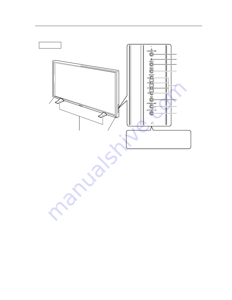
Main unit
1
Display stand
2
Remote control sensor
Point the remote control toward the remote sensor
to operate the unit.
3
STANDBY/ON indicator
This indicator is red during standby mode, and
turns to green when the unit is in the operation
mode.
Flashes green when Power-Management function
is operating.
The flashing pattern is also used to indicate error
messages.
Operation panel on the main unit
4
STANDBY/ON button
Press to put the display in operation or standby
mode.
5
KEY LOCK/UNLOCK Button (concealed button)
This switches between main unit panel and remote
control operation permitted/forbidden.
6
INPUT button
Press to select input.
7
MENU button
Press to open and close the on-screen menu.
8
ADJUST (
5
/
∞
/
3
/
2
) buttons
Use to navigate menu screens and to adjust various
settings on the unit.
Usage of cursor buttons within operations is clearly
indicated in the on-screen display.
9
SET button
Press to adjust or enter various settings on the unit.
0
SCREEN SIZE button
Press to select the screen size.
-
AUTO SET UP button
When entering a computer signal to INPUT 1 or 2,
automatically sets the POSITION and CLOCK/
PHASE to optimum values.
Note
When optional speakers have been connected,
the operation panel on the main unit will not be
operable.
Main unit
Operation panel on the main unit
Main unit
Содержание PDP 503CMX
Страница 19: ...19 Remote Control Unit Holder ...
Страница 103: ...103 Mobile Cart PDK 5014 503CMX 503MXE 433CMX 433MXE ...


