SWITCH 6
This switch bank is set through the
Function Switch Setting Mode
and the settings
are stored into Register H.
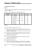
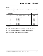
This switch sets the following player operating characteristics :
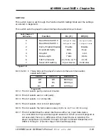
Bit 0: This bit selects 4 fields or 2 fields in still mode.
Bit 1: This bit assigns AUX 1 as the Output or as the Video Signal Indicator.
Bit 2: This bit assigns AUX 2 as the Output or as the High State Output.
Bit 3: This bit enables or disables sync insertion during squelch.
Bit 4: This bit enables or disables DOC (Drop Out Compensation).
Bit 5: This bit selects the digital or analog audio output as default. It is
usually set to Digital. If there is no Digital on the disc, the player will
default to analog.
Bit 6: This bit selects the input device to either 0 (RCU) or 1 (Serial)
Bit 7: This bit is used to set the Video Delay time to either 4.2 - 16.2 mSec. or to
15.2 - 16.2 mSec. The default setting is 4.2 - 16.2 mSec. For some
applications, especially those requiring precise audio sync, a shorter delay
time is required. (For more information, refer to Pioneer
Application Note
#177A
,
Built-In Audio Sync Lock on the LD-V8000
, 12/17/90. Contact
Pioneer LaserDisc Engineering and Technical Support, 201/327-6400. )
Chapter Two • LD-V8000 Level I & III
2-22
TP 113 v. 2.0 • 2/93
LD-V8000 Level I & III User’s Manual
Function
On (=1)
Off (=0)
0
Still Mode
4 Field
2 Field
1
AUX 1 Default Setting
Output
Video Indicator
2
AUX 2 Default Setting
Output
High State
3
Sync Out (During SQ)
Off
On
4
Drop Out Control
Off
On
5
Audio Default
Analog
Digital
6
Input Device
Device 1
Device 0
(Serial)
(RCU)
7
Video Delay Time
4.2-16.2 mSec. 15.2-16.2 mSec.
Switch Number 6
Bit Position
Figure 2-T

