


Function description
Operating Manual PSEN op2B/1 Series
1003357-EN-02
13
4
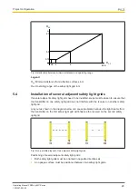
Function description
4.1
Basic function
The safety light grid consists of a transmitter and receiver, which are housed in rugged alu-
minium profiles and therefore protected from external damage.
The protected area is covered by infrared light beams, which are emitted from the transmit-
ter to the receiver. The protected field that is produced is able to detect an opaque object.
As soon as an object or part of the operator’s body interrupts the beams sent by the trans-
mitter, the output signal switching device (OSSD) is immediately switched off and the con-
nected machine is stopped immediately as a result. The object or body part must be at
least the size of the resolution covered by the safety light grid.
The functions of the safety light grid are set via DIP switches, which are located beneath a
flap on the connector side of the safety light grid. The electrical connection is made via an
M12 connector, which is positioned underneath the profiles.
The following functions are set via DIP switches:
}
Timeout muting
}
Muting
}
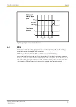
EDM
}
Restart after unit is triggered
The functions
}
Timeout muting and
}
Muting
can only be used if muting sensors are connected to the safety light grid.
The transmitter and receiver are synchronised optically, so the two units do not have to be
connected directly to each other.
The infrared beams that are transmitted and received are controlled and monitored via mi-
croprocessors, which provide the user with information about the operating state of the
safety light grid and the potential error state via LED indicators
.
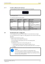
During the installation
phase, two yellow LEDs simplify the alignment of the two units.
The indicators are described under:
}
Status information during operation [
49]
}
LED support during alignment [
47]
}
Indicators for fault diagnostics


