


67
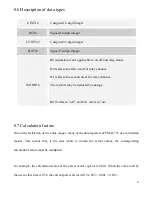
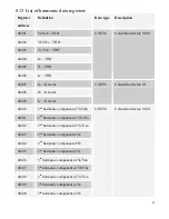
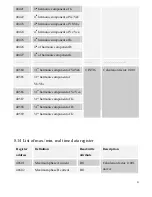
8.6 Description of data types
UINT16
Unsigned 16-digit integer
INT16
Signed 16-digit integer
LUINT32
Unsigned 32-digit integer
LINT32
Signed 32-digit integer
WORD16
Bit denotation word, applicable to on-off and relay status.
D0 refers to the first on-off or relay channel.
D1 refers to the second on-off or relay channel.
The rest bits may be deduced by analogy.
Bit 0 refers to “off”, and bit 1 refers to “on”.
8.7 Calculation factors
Due to the restriction of the value ranges, many of the data registers of PMAC735 use calculation
factors. This means that, if the user wants to obtain the actual values, the corresponding
calculation factors must be multiplied.
For example, the calculation factor of the power factor register is 0.001. When the value read by
the user at this time is 892, the current power factor will be: 892 × 0.001 = 0.892.
Содержание PMAC735
Страница 7: ...7 1 1 Pictures of the main unit Side view Rear view 1 2 Picture of the extension module Rear view...
Страница 18: ...18 B Low voltage 3 phase 3 wire delta connection 3 CTs C Low voltage 3 phase 3 wire delta connection 2 CTs...
Страница 19: ...19 D High voltage 3 phase 4 wire star connection E High voltage 3 phase 3 wire delta connection 3 CTs...
Страница 32: ...32 4 2 7 Frequency Press the key once and you will see the frequency data S1 S2 S3 S4 RL1 RL2 RL3 RL4...