


15
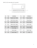
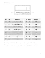
PMAC735-P: Profibus
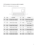
No.
Code
Definition
No.
Code
Definition
29
RB
Terminal resistor B
36
NC
Null
30
P-
Negative pole of profibus
37
NC
Null
31
P+
Positive pole of profibus
38
NC
Null
32
RA
Terminal resistor A
39
NC
Null
33
SHLD
Communication shielded
earth
40
NC
Null
34
NC
Null
41
NC
Null
35
NC
Null
42
NC
Null
Remark:
There should be an resistance (150 Ohms) connected between terminal 29 and 30.
There should be an resistance (150 Ohms) connected between terminal 31 and 32.
Содержание PMAC735
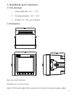
Страница 7: ...7 1 1 Pictures of the main unit Side view Rear view 1 2 Picture of the extension module Rear view...
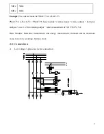
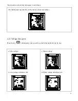
Страница 18: ...18 B Low voltage 3 phase 3 wire delta connection 3 CTs C Low voltage 3 phase 3 wire delta connection 2 CTs...
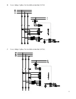
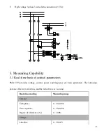
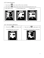
Страница 19: ...19 D High voltage 3 phase 4 wire star connection E High voltage 3 phase 3 wire delta connection 3 CTs...
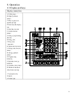
Страница 32: ...32 4 2 7 Frequency Press the key once and you will see the frequency data S1 S2 S3 S4 RL1 RL2 RL3 RL4...