


11
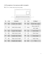
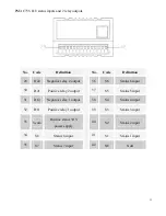
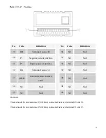
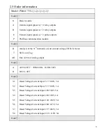
2.3 Description of the main unit terminals
No.
Code
Definition
No.
Code
Definition
1
L/+
Positive pole of power supply
15
RS485+
Positive pole of RS485
2
NC
Null
16
RS485-
Negative pole of RS485
3
N/-
Negative pole of power supply
17
SHLD
Communication shielded
earth
4
NC
Null
18
NC
Null
5
FG
Earth protection
19
NC
Null
6
NC
Null
20
A1
Positive analog output
7
\
\
21
AG
Negative analog output
8
\
\
22
VN
Voltage neutral line
9
I32
Phase C current outgoing line
23
NC
Null
10
I31
Phase C current incoming line
24
V3
Phase C voltage
11
I22
Phase B current outgoing line
25
NC
Null
12
I21
Phase B current incoming line
26
V2
Phase B voltage
13
I12
Phase A current outgoing line
27
NC
Null
14
I11
Phase A current incoming line
28
V1
Phase A voltage
Содержание PMAC735
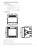
Страница 7: ...7 1 1 Pictures of the main unit Side view Rear view 1 2 Picture of the extension module Rear view...
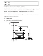
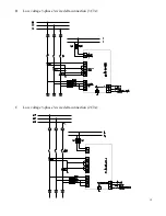
Страница 18: ...18 B Low voltage 3 phase 3 wire delta connection 3 CTs C Low voltage 3 phase 3 wire delta connection 2 CTs...
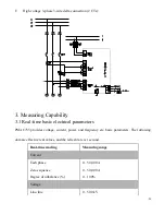
Страница 19: ...19 D High voltage 3 phase 4 wire star connection E High voltage 3 phase 3 wire delta connection 3 CTs...
Страница 32: ...32 4 2 7 Frequency Press the key once and you will see the frequency data S1 S2 S3 S4 RL1 RL2 RL3 RL4...