


21
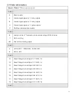
Line-neutral line
0 – 500 kV
Degree of unbalance (%)
0 – 100%
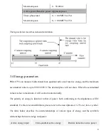
Active power/Reactive power /Apparent power
Single phase
0 - ± 100 MW/Var/VA
Total
0 - ± 100 MW/Var/VA
Power factor
Single phase
-1.000 – +1.000
Total
-1.000 – +1.000
Frequency
35 – 65 Hz
35 – 65 Hz
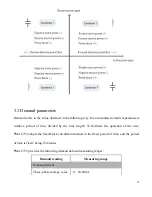
3.2 Power factor symbols
The symbols of measuring power factor conform to the stipulations of IEC, and the figure below
describes the relevant definitions.
Содержание PMAC735
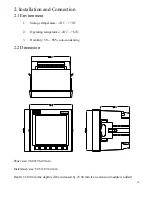
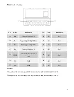
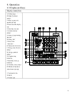
Страница 7: ...7 1 1 Pictures of the main unit Side view Rear view 1 2 Picture of the extension module Rear view...
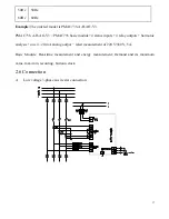
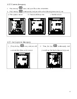
Страница 18: ...18 B Low voltage 3 phase 3 wire delta connection 3 CTs C Low voltage 3 phase 3 wire delta connection 2 CTs...
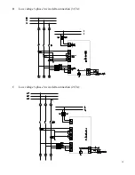
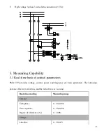
Страница 19: ...19 D High voltage 3 phase 4 wire star connection E High voltage 3 phase 3 wire delta connection 3 CTs...
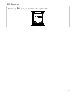
Страница 32: ...32 4 2 7 Frequency Press the key once and you will see the frequency data S1 S2 S3 S4 RL1 RL2 RL3 RL4...