5 Installation
22
Version: 1.1.2
MP129E
Q-632 Miniature Rotation Stage
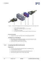
Figure 9: Example for installing the C-815.VF vacuum feedthrough. Left: Vacuum side, right: Air side
1
Q-632's connector on the vacuum side
2
Example of a vacuum feedthrough, part of a vacuum chamber
3
Sealing ring
4
C-815.VF vacuum feedthrough
5
Connector on the air side of the extension cable for connecting to the electronics.
Tools and accessories
Four M3 stainless steel countersunk screws of suitable length (ISO 7046)
Installing the vacuum feedthrough
For C-815.VF vacuum feedthrough: Install the vacuum feedthrough so that the
D-sub 15 (f) socket is in the vacuum chamber.
Pay attention to the maximum torque of 0.9 Nm.
5.4.3
Connecting the Q-632 to the Electronics
Requirements
You have read and understood the general notes on installation (p. 15).
You have installed the electronics.
You have read and understood the user manual for the electronics.
The electronics are
not
connected to the supply voltage.


