5 Installation
Q-632 Miniature Rotation Stage
MP129E
Version: 1.1.2
17
INFORMATION
The contact of the Q-632 with the protective earth conductor is made as follows:
Holes that are used for attaching the Q-632:
−
Four countersunk holes with
∅
2.2 mm /
∅
4.2 mm in the base body of the Q-632
Suitable conductive screws (p. 9)
Protective earth conductor connected to the surface that the Q-632 is mounted on
The screws are secured against unintentional loosening, e.g., with locking paint or
threadlocker
INFORMATION
Pay attention to the applicable standards for connecting the protective earth conductor.
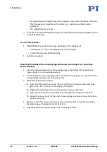
Figure 4: Bottom side of the Q-632: Two of the four
available locating holes can be used for
alignment on a surface
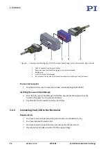
Figure 5: Top of the Q-632: The rotation stage is fixed to
the underlying surface with four screws: 4 socket
head screws (outlying countersunk holes)
Requirements
You have read and understood the general notes on installation (p. 15).
The Q-632 is
not
connected to the electronics.
You have provided a suitable underlying surface (for the required position and depth of
the holes for accommodating the screws and locating pins, see "Dimensions" (p. 40)):
−
The underlying surface must be connected to a protective earth conductor.
−
Two locating holes with
∅
1.5 mm H7 and four M2 mounting holes are available in
the surface.
−
The holes for accommodating the screws have to be sufficiently conductive to
ensure that the protective earth conductor functions properly.


