Modem
: Indicates that your computer must dial into the unit via your modem. When more
than one unit requiring a modem connection is selected on the real-time screen, the software
will periodically connect to each unit. Use the ConnectOnTime and ConnectOffTime slots to
specify how long your modem should connect to the selected unit(s). ConnectOffTime is the
intercall time from when the selected unit disconnects until the next unit connects. The param-
eters of each are specified in minutes.
Note
: If you are connecting to only one unit via modem and want the connection
to be continuous, select Local as the connect type.
Radio
: Means that you are communicating with your units via radio modem. In this scenario,
the computer will poll the selected I/O points from each unit on a continuous basis.
When the Real-time screen runs, it will connect to all units connected via serial port first, fol-
lowed by units on a radio network, and lastly units connected via modem. The order of calls for
modem units is based on the order in which they were added to the realtime screen during the
initial design stage.
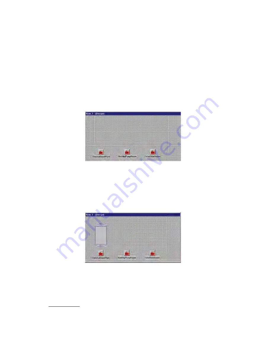
Figure 6: Palette with connected units
PLACING OBJeCTS ON THe PALeTTe
A variety of standard objects can be accessed with the tabbed categories: Electrical, Rotating,
Containers, Valves, and Gauges. To place objects on the Palette, select one of the tabs and
click on an object. For example, from the Container Tab, click on the
ContainerVessel
object.
Now click on the palette. The Vessel should appear on the palette as shown below.
Figure 7: Vessel object
Next, edit the properties of the vessel to assign it to an I/O value. Adjust the minimum and
maximum values, set the colors, and so forth. A list of properties with descriptions is provided
below.
Basic Properties
BackGndMode: There are 2 settings:
bmOpaque
and
bmTransparent
. The
bmOpaque
setting will display the background color of the component or image as specified
by the Color property. The
bmTransparent
setting will display the component back-
ground as transparent so that any component, image or background will be visible.
14-4
SCADA 3000 User’s Manual
Содержание Sensaphone SCADA 3000
Страница 1: ...Sensaphone SCADA 3000 User s Manual Version 2 34...
Страница 6: ...vi SCADA 3000 User s Manual...
Страница 10: ...x SCADA 3000 User s Manual...
Страница 30: ...1 6 SCADA 3000 User s Manual...
Страница 48: ...4 6 SCADA 3000 User s Manual...
Страница 70: ...9 8 SCADA 3000 User s Manual...
Страница 122: ...12 8 SCADA 3000 User s Manual...
Страница 190: ...15 30 SCADA 3000 User s Manual...
Страница 211: ...lead 1 lag 0 else lead 0 lag 1 16 21 Chapter 16 Programming in C...
Страница 212: ...16 22 SCADA 3000 User s Manual...
Страница 236: ...21 8 SCADA 3000 User s Manual...
Страница 248: ...22 12 SCADA 3000 User s Manual...
Страница 258: ...23 10 SCADA 3000 User s Manual...
Страница 274: ...25 8 SCADA 3000 User s Manual...
Страница 288: ...27 8 SCADA 3000 User s Manual...
Страница 294: ...28 6 SCADA 3000 User s Manual...
Страница 296: ...A 2 SCADA 3000 User s Manual...
Страница 302: ...D 2 SCADA 3000 User s Manual...
Страница 318: ...I 2 SCADA 3000 User s Manual...
Страница 320: ...J 2 SCADA 3000 User s Manual...
Страница 322: ...K 2 SCADA 3000 User s Manual...
Страница 335: ...Test Log...
Страница 336: ......


