background image

IL PB BK DI8 DO4/EF-PAC

A-6

PHOENIX CONTACT

7725_en_01

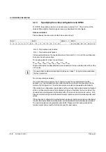
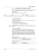
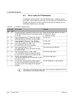
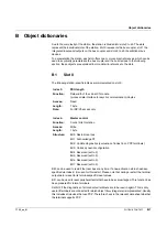
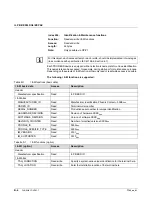
Following a configuration block:

Following a failsafe block:

If one or more function blocks are present, a header byte for the function block follows:

After that the function blocks are decoded:

Table A-10

Parameters for the I/O devices byte 1

Byte

Bit

Meaning

Byte 1

Bit 7 to bit 6

00: Start block ID for device

Bit 5 to bit 4

Configuration

00: No configuration (e.g., DO)

01: Permanent configuration

10: Temporary configuration

Bit 3 to bit 2

Failsafe value

00: No failsafe value (e.g., DI)

01: Output zero

10: Maintain value

11: Apply value from data field

Bit 1

Extended functions

0: No function block

1: Function block (also several)

Bit 0

Activation

0: Activated

1: Disabled

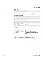
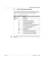
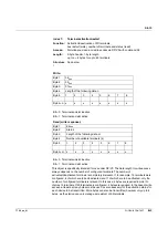
Byte x

Bit 7 to bit 6

01: Configuration block ID

Bit 5 to bit 0

Length of the data block

Byte x+1 to n

n data bytes

Byte x

Bit 7 to bit 6

10: Failsafe value block ID

Bit 5 to bit 0

Length of the data block

Byte x+1 to n

n data bytes

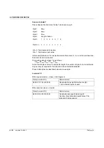
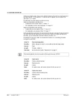
Byte x

Bit 7 to bit 6

11: Function block ID

Bit 5 to bit 0

Entire function block length

An additional byte is automatically used if the total length 

of the function block is exceeded. This byte specified the 

actual length of the function block.

The first byte (header byte for the function blocks) is set 

to FF

hex

.

Содержание IL PB BK DI8 DO4/EF-PAC

Страница 1: ...AUTOMATION UM EN IL PB BK DI8 DO4 EF PAC Order No User manual Diagnostic and firmware functions of the IL PB BK DI8 DO4 EF PAC bus coupler ...

Страница 2: ......

Страница 3: ... manual is valid for AUTOMATION 7725_en_01 PHOENIX CONTACT 12 2009 Diagnostic and firmware functions of the IL PB BK DI8 DO4 EF PAC bus coupler UM EN IL PB BK DI8 DO4 EF PAC 01 Designation Order No IL PB BK DI8 DO4 EF PAC 2692322 User manual ...

Страница 4: ...r operation and ease of use This is the safety alert symbol It is used to alert you to potential personal injury hazards Obey all safety messages that follow this symbol to avoid possible injury or death DANGER This indicates a hazardous situation which if not avoided will result in death or serious injury WARNING This indicates a hazardous situation which if not avoided could result in death or s...

Страница 5: ...ng errors in the information cannot be ruled out Phoenix Contact does not offer any guarantees as to the reliability accuracy or completeness of the information All information made available in the technical data is supplied without any accompanying guarantee whether expressly mentioned implied or tacitly assumed This information does not include any guarantees regarding quality does not describe...

Страница 6: ... such rights shall not be excluded How to contact us Internet Up to date information on Phoenix Contact products and our Terms and Conditions can be found on the Internet at www phoenixcontact com Make sure you always use the latest documentation It can be downloaded at www phoenixcontact net download Subsidiaries If there are any problems that cannot be solved using the documentation please conta...

Страница 7: ...on in DP V1 mode 3 4 3 4 1 The communication mechanism 3 4 3 4 2 Examples 3 7 3 5 Acyclic communication in DP V0 mode via process data 3 13 3 5 1 Mechanism for transmission in the process data 3 13 3 5 2 Examples for VC1 services 3 18 4 Dynamic configuration 4 1 4 1 Empty spaces 4 1 4 2 Principle of dynamic configuration 4 4 4 3 Startup 4 6 4 3 1 Planning configuration 4 6 4 3 2 Options for specif...

Страница 8: ...IL PB BK DI8 DO4 EF PAC ii PHOENIX CONTACT 7725_en_01 B Object dictionaries B 1 B 1 Slot 0 B 1 B 2 Slot 1 B 8 B 3 Slots 2 to 63 B 8 ...

Страница 9: ... O modules can also be used The PROFIBUS bus coupler can be ordered using Order No 2692322 Connectors labeling fields and an end plate are supplied as standard Figure 1 1 The IL PB BK DI8 DO4 EF PAC PROFIBUS bus coupler Scope of supply PROFIBUS bus coupler 1 Connectors 2 Labeling field 3 End plate 4 PROFIBUS PR OF IBU S DP X1 IL PB BK DI8 DO4 EF PAC Order No 2692322 0 2 4 6 8 x10 10 12 0 2 4 6 8 9...

Страница 10: ... Four digital outputs Diagnostic and status LEDs Automatic baud rate detection on the local bus 500 kbps or 20 Mbps Additional features of EF version Approved for PROFIsafe IO Link call firmware 2 0 or later When using the bus coupler in a PROFIsafe system please refer to the documentation for the safety terminals used see PROFIsafe application notes on page 5 1 For additional information about th...

Страница 11: ...y the error type is indicated by the specific flashing codes of the LEDs on the bus coupler 2 1 Activating deactivating the diagnostic formats The diagnostic format can be set as a parameter on the terminal You can select either IL PB BK DI8 DO4 Format Status PDU Diagnostics or ID Specific Diagnostics By default IL PB BK DI8 DO4 Format is activated The Status PDU Diagnostics format must be set for...

Страница 12: ...of bytes in a block depends on the station structure Table 2 1 IL PB BK DI8 DO4 PAC format diagnostics Byte Bit 7 Bit 6 Bit 5 Bit 4 Bit 3 Bit 2 Bit 1 Bit 0 Meaning Block 1 1 X X X X X X X X Station status 1 2 X X X X X X X X Station status 2 3 X X X X X X X X Station status 3 4 X X X X X X X X PROFIBUS master address 5 0 0 0 0 1 0 1 1 Manufacturer ID high byte 0Bhex 6 0 1 0 1 0 0 0 0 Manufacturer ...

Страница 13: ...D 62 ST LD 61 Status local bus devices 61 to 63 Block 4 36 1 0 Slot Channel specific diagnostics header slot 1 37 IO Channel IN OUT and channel number slot 1 38 CT ET Channel and error type slot 1 1 0 Slot number Channel specific diagnostics header slot 2 IO Channel IN OUT and channel number slot 2 CT ET Channel and error type slot 1 1 0 Slot number Channel specific diagnostics header slot 10 IO C...

Страница 14: ...ate 1 500 kbaud 2 2 Mbaud 72 X X X X X X X X Diagnostic location FF OK 73 X X X X X X X X User ID code 1st local bus device with error 74 X X X X X X X X User length code 1st local bus device with error 75 X X X X X X X X LB state high byte 76 X X X X X X X X LB state low byte 77 0 0 0 0 0 0 0 X System limit violated 78 X X X X X X X X Number of accessible local bus devices Table 2 1 IL PB BK DI8 ...

Страница 15: ...elegram M Slave assigned to another master Table 2 3 Byte 2 Status 2 7 6 5 4 3 2 1 0 X Slave must be reparameterized X Static diagnostics 1 Fixed to 1 for DP operation X Watchdog activated X Freeze command received X Sync command received 0 Reserved M Slave is deactivated Table 2 4 Byte 3 Status 3 7 6 5 4 3 2 1 0 0 0 0 0 0 0 0 Reserved X Slave has more diagnostic information than displayed in the ...

Страница 16: ...ifier SP equals 1 in the event of a faulty state The specifier equals 2 if the terminal changes from a faulty state to an error free state If the specifier equals 0 the state has not changed In the first byte of the block bits 0 to 5 specify the number of local bus devices and therefore the length of the Status PDU block The minimum length of this block is 5 4 byte header 1 byte 4 devices maximum ...

Страница 17: ...nostics must be activated on the bus coupler Block 5 Revision diagnostics Indicates the firmware version e g C3hex Version 3 IO 00bin Reserved IO 01bin Input IO 10bin Output IO 11bin Input and output Channel Channel number of the relevant channel 0 to 63 CT 000bin Reserved CT 001bin 1 bits CT 010bin 2 bits CT 011bin 4 bits CT 100bin 1 byte CT 101bin 1 word CT 110bin 2 words CT 111bin Reserved ET 0...

Страница 18: ... coupler is always counted as a local bus device LD In the event of an error on the bus coupler the corresponding bits for local bus device 1 are set in the diagnostics Table 2 7 Status PDU diagnostics incl error codes Byte X Bit 7 Bit 6 Bit 5 Bit 4 Bit 3 Bit 2 Bit 1 Bit 0 Meaning Block 1 1 X X X X X X X X Station status 1 2 X X X X X X X X Station status 2 3 X X X X X X X X Station status 3 4 X X...

Страница 19: ... for F Parameters or the documentation of the individual module Table 2 8 ID specific terminal diagnostics Byte X Bit 7 Bit 6 Bit 5 Bit 4 Bit 3 Bit 2 Bit 1 Bit 0 Meaning Block 1 1 X X X X X X X X Station status 1 2 X X X X X X X X Station status 2 3 X X X X X X X X Station status 3 4 X X X X X X X X PROFIBUS master address 5 0 0 0 0 1 0 1 1 Manufacturer ID high byte 0Bhex 6 0 1 0 1 0 0 0 0 Manufac...

Страница 20: ...ror no are indicated by flashing codes of the local diagnostic LEDs LED FS and LED FN Figure 2 2 Local diagnostic indicators on the bus coupler 0 2 4 6 8 x10 10 12 0 2 4 6 8 9 x1 PROFIBUS PRO FIBU S DP X1 IL PB BK DI8 DO4 EF PAC Order No 2692322 I1 1 3 2 4 UL US UM BF FS FN PWR D E O1 1 3 2 4 I2 7 5 8 6 BF DIA UL US UM BF FS FN PWR 7725A002 ...

Страница 21: ...k the number of parameters 4 The PD PCP module appears several times in the configuration Check the configuration with regard to the number of PD PCP modules There must only be one PD PCP module Except for PROFIsafe terminals these have two PD PCP modules 5 The data block length was exceeded Check the number of terminals 6 A parameter block is not complete Check the structure of the parameters for...

Страница 22: ... not correspond to the length code of the terminal Determine the exact error location using the terminal specific diagnostics in your control system Check the configuration in the hardware configurator 6 The data length of the parameter block is faulty Check the number of parameters The parameter length must not be longer than the output data length of the relevant terminal 7 PROFIBUS address of t...

Страница 23: ...rror cause 6 Safety terminal error Activate Status PDU diagnostics when parameterizing the bus coupler in your controller and determine the exact error location and error cause 7 More than 62 Inline devices are connected Re configure the station structure with regard to the maximum permissible number of Inline devices 8 More than 16 PCP devices are connected Reduce the number of PCP devices in the...

Страница 24: ...IL PB BK DI8 DO4 EF PAC 2 14 PHOENIX CONTACT 7725_en_01 ...

Страница 25: ...responding read and write access rights are therefore defined for the C1 master As it already has a connection to the slave during cyclic data traffic the C1 master does not have to establish an explicit connection using Initiate but can communicate with the slave directly via Read and Write 3 2 Acyclic communication via the Class 2 master C2 master C2 master For communication in the C2 master the...

Страница 26: ...nected to a PLC via a bus interface The device versions are standardized according to the Drives profile Figure 3 1 Application example Device parameters Device parameters are data from intelligent field devices PCP devices which is required for the startup phase of machines and systems Once it has been entered this data only has to be modified upon a change in the parameterization or in the event...

Страница 27: ...to identify the object Object description The object description includes all the properties of the object such as data type object type name etc Object types There are various different object types Simple variable Simple variable type objects Examples include measured values the time or status of a terminal Array Array type objects i e several simple variable objects of the same type which are g...

Страница 28: ...as a DP V1 write request PCP read to slot x b Receive the DP V1 write response often automatically via the master 2 a Send a DP V1 read to slot x b Receive the DP V1 read response usually automatically via the master Write 1 a Send the request as a DP V1 write request PCP write to slot x b Receive the DP V1 write response often automatically via the master 2 a Send a DP V1 read to slot x b Receive...

Страница 29: ...sitive Slot DP V1 index DP V1 length Error data PCP DP V1 The Data PCP DP V1 is optional depending on the service and has the following structure The meaning of the individual parameters is as follows DP V1 service In the request there is a distinction between DP V1 read 5Ehex and DP V1 write 5Fhex in the error response there is a distinction between DEhex read error and DFhex write error Table 3 ...

Страница 30: ...itten or read Read PCP 06hex Write PCP 07hex Object data This is only the contents of an object The length and scope of the data has already been described by DP V1 length Invoke ID The Invoke ID is used for some I O devices Check this in the relevant data sheet Index high and Index low This specifies the object index of the addressed PCP object in two bytes For example for index 2300hex the value...

Страница 31: ... for example Table 3 4 Object dictionary for the IB IL AI4 EF Table 3 5 Object description Objects 4 and 4 on the bus coupler are also used in these examples For an explanation regarding these objects please refer to section Object dictionaries on page B 1 Index Data type N L Meaning Object name Rights 0080hex Array of Unsigned 16 6 2 Config Table rd wr N Number of elements rd Read access permitte...

Страница 32: ...he request The response indicates that the command has been received As can be seen in Section Object dictionaries on page B 1 the local bus is restarted with bit 0 01hex at index 4 slot 0 Read request master slave Data Data structure 5E 00 05 20 DP V1 Read Slot Index Maximum Length Read request slave master Data Data structure 5E 00 05 06 03 01 00 04 01 00 DP V1 read Slot Index Actual length 6 by...

Страница 33: ...us indicates that communication was error free Write request master slave Data Data structure 5F 03 2F 05 06 00 00 80 00 DP V1 write Slot Index Length Read PCP request Invoke ID PCP index high PCP index low PCP subindex Write response slave master Data Data structure 5F 03 2F 05 DP V1 write Slot Index Length Read request master slave Data Data structure 5E 03 2F 20 DP V1 Read Slot Index Maximum Le...

Страница 34: ... 2F 08 07 00 00 80 03 02 03 01 DP V1 write Slot Index Length Write PCP request Invoke ID PCP index high PCP index low PCP subindex Length of PCP object data PCP object data Write response slave master Data Data structure 5F 03 2F 08 DP V1 write Slot Index Length Read request master slave Data Data structure 5E 03 2F 20 DP V1 Read Slot Index Maximum Length Read response slave master Data Data struc...

Страница 35: ... last 2 bytes are also part of the PCP error data however they are not used in this example If they do not equal zero refer to the relevant I O device data sheet for more detailed information Write request master slave Data Data structure 5F 03 2F 05 06 00 01 80 00 DP V1 write Slot Index Length Read PCP request Invoke ID PCP index high PCP index low PCP subindex Write response slave master Data Da...

Страница 36: ...age is sent by DP V1 whereby error code D2 stands for Terminal does not have PCP See also Section Error codes for DP V1 and VC1 communication on page A 3 Write request master slave Data Data structure 5F 02 2F 05 06 00 00 80 00 DP V1 write Slot Index Length Read PCP request Invoke ID PCP index high PCP index low PCP subindex Write response slave master Data Data structure DF 80 D2 00 DP V1 write e...

Страница 37: ...g active process data exchange it is possible to assign the VC1 module sequentially to different modules with communication objects and to exchange parameter data parallel to the process data Process data width The process data width occupied by the VC1 module in the process data channel can be selected from 4 to 16 words in increments of 2 words This means that communication objects can be used e...

Страница 38: ...tart fragment Byte 1 7 6 5 4 3 2 1 0 Request Response 0 0 Fragmenta tion Action Bit 7 Request Response 0 Request 1 Response Bits 6 to 5 Fragment type 00 Start fragment Bit 4 Fragmentation 0 Not fragmented 1 Fragmented Bits 3 to 0 Action 00hex No action clear 01hex to 02hex Reserved 03hex Read IL PB BK DI8 DO4 EF 04hex Write IL PB BK DI8 DO4 EF 05hex Reserved 06hex Read PCP I O device 07hex Write P...

Страница 39: ...Byte 1 7 6 5 4 3 2 1 0 Request Response 0 1 Fragment number 01hex 1Fhex Bit 7 Request Response 0 Request 1 Response Bits 6 to 5 Fragment type 01 Continue fragment Bits 4 to 0 Counter 01hex to 1Fhex fragment number Byte 1 Service Byte 2 Data block if required Byte n Data block if required Byte 1 7 6 5 4 3 2 1 0 Request Response 1 0 Reserved Bit 7 Request Response 0 Request 1 Response Bits 6 to 5 Fr...

Страница 40: ... occurred if the value of the status byte does not equal 00hex Byte 1 Service Byte 2 Error code if required Byte n Error code if required Byte 1 7 6 5 4 3 2 1 0 Request Response 1 1 Reserved Bit 7 Request Response 0 Request 1 Response Bits 6 to 5 Fragment type 11 Abort error fragment Bits 4 to 0 Reserved Communication can be reset at any time using 00hex and 60hex Byte 1 Service mirrored request w...

Страница 41: ...ex 4hex on the bus coupler 00hex is Index high and 04hex is Index low Sub index When working with a PCP object the subindex can be used to select a specific element from an array or record Therefore the subindex should be specified when accessing I O devices The bus coupler has no arrays or records so subindex 0 should be specified Length This value specifies how many bytes of object data object c...

Страница 42: ... via Clear Read request master slave Data 8 words VC1 Data structure 03 00 00 00 05 00 I 00 00 00 00 00 00 00 00 00 00 Read request bus coupler Slot Invoke ID Index high Index low Subindex 10 bytes unused Read response slave master Data 8 words VC1 Data structure 83 00 06 03 01 00 04 01 00 I 00 00 00 00 00 00 00 Read response bus coupler Status Actual length 6 bytes of object data 7 bytes unused C...

Страница 43: ...rds VC1 Data structure 04 00 00 00 04 00 01 01 I 00 00 00 00 Write request bus coupler Slot Invoke ID Index high Index low Subindex Length 1 byte of data 4 bytes unused Write response slave master Data 6 words VC1 Data structure 84 00 I 00 00 00 00 00 00 00 00 00 00 Write response bus coupler Status 10 bytes unused Clear request master slave Data 6 words VC1 Data structure 00 I 00 00 00 00 00 00 0...

Страница 44: ...at communication was error free Read request master slave Start fragment Data 4 words VC1 Data structure 06 03 00 00 80 00 I 00 00 Read request I O Slot Invoke ID Index high Index low Subindex 2 bytes unused Read response slave master Data 4 words VC1 Data structure 96 00 0C 03 01 03 00 03 Read response Status Length 5 bytes of object data Read request master slave Start fragment acknowledgment Da...

Страница 45: ... or Clear can be sent Acknowledgment of the last fragment or Clear Read request master slave End fragment acknowledgment Data 4 words VC1 Data structure C0 I 00 00 00 00 00 00 00 End fragment acknowledgment 7 bytes unused Read response slave master Data 4 words VC1 Data structure 00 00 00 00 00 00 00 00 Clear Clear request master slave Data 4 words VC1 Data structure 00 I 00 00 00 00 00 00 00 Clea...

Страница 46: ...PCP object data Write response slave master Data 4 words VC1 Data structure 17 I 00 00 00 00 00 00 00 Write response 7 bytes unused Write request master slave 1st continue fragment Data 4 words VC1 Data structure 21 00 03 01 03 00 03 01 1 Continue fragment 7 bytes PCP object data Write response slave master Data 4 words VC1 Data structure 21 I 00 00 00 00 00 00 00 Response 7 bytes unused Write req...

Страница 47: ... however they are not used in this example If they do not equal zero refer to the relevant device data sheet for more detailed information The communication data can be reset to the initial state via Clear Read request master slave Start fragment Data 4 words VC1 Data structure 06 03 00 01 80 00 I 00 00 Read request I O Slot Invoke ID Index high Index low Subindex 2 bytes unused Write response sla...

Страница 48: ... DP V1 and VC1 communication on page A 3 The communication data can be reset to the initial state via Clear Read request master slave Data 4 words VC1 Data structure 06 02 00 00 80 00 I 00 00 Read request Slot Invoke ID Index high Index low Subindex 2 bytes unused Write response slave master Data 4 words VC1 Data structure 86 D2 00 00 00 00 00 00 Read response Status 6 bytes unused Clear request m...

Страница 49: ...onfiguration levels You can configure the maximum configuration level and thus also reserve memory in the PLC However optional terminals do not have to be connected They can be deactivated in the configuration If the station is subsequently extended to include previously deactivated terminals the new terminals can be connected and activated in the hardware configurator Figure 4 1 Configuration tab...

Страница 50: ...d to specify whether a device should be active or inactive see Figure 4 3 Figure 4 3 Activating deactivating a terminal Following activation deactivation the configuration can be saved translated and downloaded as usual Please note that adjustments to the configuration and actual structure are also carried out for inactive terminals A message is displayed if deactivated terminals are connected ...

Страница 51: ... 4 3 Depending on the terminal type substitute values DO and AO to be output in the event of an error can also be set at this point for example Furthermore inputs AI can be parameterized This is also carried out via the dialog box shown in Figure 4 3 ...

Страница 52: ...evices The only requirement is that they are part of the maximum configuration Three indices on the bus coupler are used for handling Index 4 General control bits Index 6 Activation deactivation of devices and slots All settings are stored in the volatile memory Thus easy replacement is ensured The terminal does not have to be parameterized in advance Access Write Function Details under Slot 0 on ...

Страница 53: ... which devices are active inactive Deactivation via the parameter telegram reservation of empty spaces is also indicated here In addition the bus is reset Structure Length of 5 to 12 bytes maximum Byte 1 08hex Byte 2 00hex Byte 3 07hex Byte 4 Length of data n Byte 5 1 2 3 4 5 6 7 8 Byte 4 n x x x x x x x x Bit 0 Terminal and slot inactive Bit 1 Terminal and slot active ...

Страница 54: ...ta interface Index 7 is intended to be used if no DP V1 master exists or if both the specification and the bus restart are to be implemented using a single service in the process data interface If the process data interface is used the effort required is minimized For access via process data configure the VC1 process data interface This is the PD PCP x words x 4 6 16 module It can be specified as ...

Страница 55: ...minals no data is exchanged as long as the connected configuration does not correspond to the available activated terminals Specify the configuration connected to the station in a non volatile memory via index 6 or index 7 Data exchange is started For the second option the example from the figure on page 4 6 is used and the DI8 as well as the DO8 are deactivated via DP V0 and DP V1 In each case th...

Страница 56: ...s the configuration The activation status on index 6 is evaluated automatically If the active bus configuration is extended and if previously inactive terminals are attached at the end these terminals are first activated via index 6 Next time the bus is started the new terminals are integrated into the data traffic The bus can be started via index 4 bit 0 Please note that during a restart the term...

Страница 57: ...master slave End fragment Data 4 words VC1 Data structure 40 00 00 00 00 00 00 00 Write 7 bytes of data Write response slave master Data 4 words VC1 Data structure 84 I 00 00 00 00 00 00 00 Write response Status 6 bytes unused Write request master slave Start fragment Data 8 words VC1 Data structure 14 00 00 00 06 00 08 F2 00 00 00 00 00 00 00 I 00 Write Slot Invoke ID Index high Index low Subinde...

Страница 58: ...d for the terminals to be activated deactivated These 5 data bytes are described below as an example 4 words VC1 Byte 1 08hex Byte 2 00hex Byte 3 07hex Byte 4 Length of data n Byte 5 1 2 3 4 5 6 7 8 Byte 4 n x x x x x x x x Bit 0 Terminal and slot inactive Bit 1 Terminal and slot active Write request master slave Start fragment Data 4 words VC1 Data structure 08 00 07 01 F2 I 00 00 00 Read write I...

Страница 59: ...ntinuously until it is matches the configuration The activation status on index 6 is evaluated automatically If the active bus configuration is extended and if previously inactive terminals are attached at the end these terminals are first activated via index 6 Next time the bus is started the new terminals are integrated into the data traffic The bus can be started via index 4 bit 0 Please note t...

Страница 60: ...d For additional information and examples regarding communication via the process data interface as well as DP V1 please refer to Section Acyclic communication DP V1 and PCP on page 3 1 The PD PCP x words process data interface module does not have to be configured for normal operation It is only required if you wish to access objects such as index 6 via the process data If you wish to use the PD ...

Страница 61: ...er with safe and non safe I O devices At present the following PROFIsafe modules are available IB IL 24 PSDI 8 PAC IB IL 24 PSDO 8 PAC IB IL 24 PSDOR 4 PAC IB IL 24 PSDO 4 4 PAC The modules map 4 words of process data to the local bus and obtain the F Parameters and iParameters from the parameter telegram via a 63 byte parameter block The settings are provided in the GSD file The GSD file electron...

Страница 62: ...IL PB BK DI8 DO4 EF PAC 5 2 PHOENIX CONTACT 7725_en_01 ...

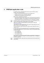
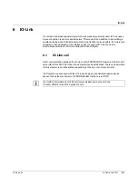
Страница 63: ... device automatically switches to SIO mode Standard Input Output 6 1 IO Link call Direct communication between the IO Link client PROFIBUS DP master and the IO Link server IB IL IOL4 DI2 PAC Inline IO Link master can be established There can be multiple IO Link masters in an Inline station depending on the amount of process data IOLD objects are accessed with the IO Link call being a standardized ...

Страница 64: ...IL PB BK DI8 DO4 EF PAC 6 2 PHOENIX CONTACT 7725_en_01 ...

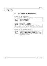
Страница 65: ...access denied Meaning The object has limited access rights Cause It may be a read only object or it may be password protected Remedy Check the access rights in the object description Table A 3 06hex 05hex Object attribute inconsistent Meaning A service parameter was specified with an impermissible value Cause E g an incorrect length specification or an impermissible subindex Remedy Check the param...

Страница 66: ...services are supported for this object Table A 5 06hex 07hex Object non existent Meaning The object does not exist Cause The Index parameter probably contains an invalid value Remedy Check the object index in the object description and send the service again Table A 6 08hex 00hex Application error Meaning Terminal specific error message not a communication error Cause Remedy Refer to your terminal...

Страница 67: ...1 communication Error_Code_1 Error_Code_2 Meaning B0hex 0 Index invalid B1hex 0 Invalid data length when writing B2hex 0 Invalid device number B5hex 0 Status conflict last read write not finished yet B6hex 0 Access to device or index not permitted B7hex 0 Invalid parameter C3hex 0 Internal resource not available D1hex 0 PCP connection not established D2hex 0 PCP not supported D4hex 0 Incorrect ser...

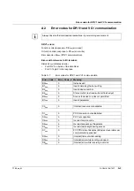
Страница 68: ...66 42 Invalid parameterization of F_Source_Address Addresses 0000hex and FFFFhex are not permitted Correct value 67 43 Invalid parameterization of F_WD_Time A monitoring time of 0 ms is not permitted Correct value 68 44 Invalid parameterization of F_SIL The required SIL cannot be supported by the safety module F module Use device with the required SIL 69 45 Invalid parameterization of F_CRC_Length...

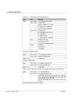
Страница 69: ...11 Control byte Bit 7 0 Hide channel specific diagnostics 1 Show channel specific diagnostics Bit 6 0 Do not rotate DI32 and DO32 data 1 Rotate DI32 and DO32 data Bit 5 0 SET_PRM does not overwrite dynamic configuration 1 SET_PRM overwrites dynamic configuration Bit 4 0 Do not rotate DI16 and DO16 data 1 Rotate DI16 and DO16 data Bit 3 Reserved set to 0 Bit 2 Reserved set to 0 Bit 1 0 Automaticall...

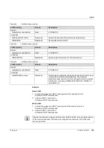
Страница 70: ...e g DI 01 Output zero 10 Maintain value 11 Apply value from data field Bit 1 Extended functions 0 No function block 1 Function block also several Bit 0 Activation 0 Activated 1 Disabled Byte x Bit 7 to bit 6 01 Configuration block ID Bit 5 to bit 0 Length of the data block Byte x 1 to n n data bytes Byte x Bit 7 to bit 6 10 Failsafe value block ID Bit 5 to bit 0 Length of the data block Byte x 1 t...

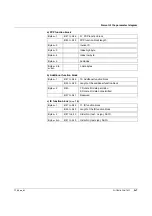
Страница 71: ...yte x 4 Index low byte Byte x 5 Subindex Byte x 6 to x 6 n n data bytes Byte x 1 Bit 7 to bit 6 10 Additional function block Bit 5 to bit 0 Length of the additional function block Byte x 2 Bit 0 1 Rotate I O data permitted 0 Rotate I O data not permitted Bit 7 to bit 1 Reserved Byte x 1 Bit 7 to bit 6 11 ID function block Bit 5 to bit 0 Length of the ID function block Byte x 2 Bit 7 to bit 0 Order...

Страница 72: ...IL PB BK DI8 DO4 EF PAC A 8 PHOENIX CONTACT 7725_en_01 ...

Страница 73: ...hat during a restart the terminal output data is reset to its terminal specific reset values Bit 1 can be used to reset peripheral faults that have to be acknowledged This function has been prepared for future terminals Set bit 2 if the diagnostics of all connected terminals are to be read in again This is only useful if terminals are connected for which object 18hex diag state is implemented Usua...

Страница 74: ...s way both options are available Restart with original configuration Restart with last dynamic configuration Bit 0 Terminal and slot inactive Bit 1 Terminal and slot active Index 5 PCP status Function Position and communication status of PCP terminal Access Read Length 3 bytes per PCP terminal 48 bytes maximum Structure Byte 1 Position in the station slot number Byte 2 Status of PCP connection 00h...

Страница 75: ...e transmitted More bytes can also be transmitted however only up to 8 bytes as the station can only manage a maximum of 63 terminals Index 7 Terminal activation restart Function Activation deactivation of I O terminals bus restart write number of terminals and status read Access Simultaneous read and write access via DP V0 with command 08 Length 3 byte header 1 byte length up to n 8 bytes for up t...

Страница 76: ...ut data and the real status in the input data in addition to simply specifying the activation you can determine which terminals are present or not An example for access to index 7 is described in Section 4 3 3 Specifying the active configuration via DP V0 Index 12 Terminal diagnostics Function Station diagnostics byte 7 and up without standard diagnostics Access Read Length 72 bytes maximum Struct...

Страница 77: ...le error count Function Cycle counter all faulty ID cycles Access Read and write Length 8 bytes Note For write access all counters index 20 to 25 are set to 0 Index 24 Data cycle count Function Cycle counter all data cycles Access Read and write Length 8 bytes Note For write access all counters index 20 to 25 are set to 0 Index 25 Data cycle error count Function Cycle counter all faulty data cycle...

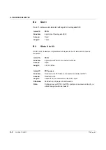
Страница 78: ...1 I M functions basic data I M basic data Access Description Header Manufacturer specification Read IL PB BK DIO I M block MANUFACTURER_ID Read Manufacturer identification Phoenix Contact 00B0hex ORDER_ID Read Terminal order number SERIAL_NUMBER Read Production serial number for unique identification HARDWARE_REVISION Read Revision of hardware XXXXhex SOFTWARE_REVISION Read Version of software XXX...

Страница 79: ...write Not specified at the moment Table B 3 I M3 functions option I M3 option Access Description Header Manufacturer specification Read IL PB BK DIO I M block DESCRIPTOR Read write Specify a general comment on the terminal here Table B 4 I M4 functions option I M4 option Access Description Header Manufacturer specification Read IL PB BK DIO I M block SIGNATURE security Read write The hardware conf...

Страница 80: ...ut data of the integrated DI8 Access Read Length 1 byte Index 13 PD IN Function Input data on the slot of connected terminals Access Read Length 0 to 128 bytes Index 47 PCP access Function Read and write PCP data on connected terminals via DP V1 Access Read and write Length Depends on the command and the PCP object Structure See Section 3 4 page 3 4 and onwards Note During access via DP V0 the PCP...

Отзывы: