Acyclic communication (DP/V1 and PCP)
7725_en_01
PHOENIX CONTACT
3-13
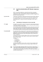
3.5
Acyclic communication in DP/V0 mode via process
data
DP/V1 communication is relatively new compared to cyclic DP/V0 communication.
However, the service life of control systems and plants is so long that extensions and
modifications are made. In many cases, the control system is not DP/V1-compatible, but is
expected to operate complex devices.
Acyclic services
Consequently, it is possible to operate acyclic services within the process data. That means
even a control system that does not have DP/V1 can operate more complex terminals.
For additional information about PCP communication, please refer to Sections "PCP
communication basics" on page 3-2 and "Acyclic communication in DP/V1 mode" on
3.5.1
Mechanism for transmission in the process data
VC1 module
Transmission is via a virtual C1 module (VC1 module). A C1 module should be selected in
the hardware configurator in the same way as "normal" I/O devices and therefore specified
in the configuration and parameter telegram.
The VC1 module is only a virtual device because the process data can be used to transmit
communication data (PCP) and is not linked to a specific module. During active process
data exchange, it is possible to assign the VC1 module sequentially to different modules
with communication objects and to exchange parameter data parallel to the process data.
Process data width
The process data width occupied by the VC1 module in the process data channel can be
selected from 4 to 16 words in increments of 2 words. This means that communication
objects can be used even if resources are limited. If there are sufficient free resources, a
data width of up to 16 words can be used, providing the same ease of operation as for
DP/V1 communication.
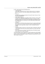
As the data width of the VC1 module is between 4 and 16 words, but the user data can be
up to 72 bytes (36 words) per communication, it may be necessary to split the data and
transmit it in several steps.
This leads to:
–
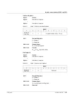
Start fragment
–
Continue fragment
–
End fragment
–
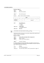
Error or abort fragment
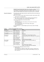
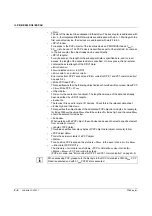
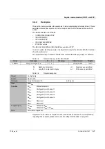
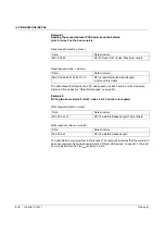
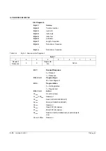
Each fragment contains a service byte, which is used for the precise assignment of the
fragment. The individual fragments and the service byte are explained in detail in the
following.
The VC1 module (listed in the GSD as "PD PCP x words") may be configured at any
position after the IL PB BK DI8 DO4/EF-PAC bus coupler. We recommend configuring
the VC1 device in the last position. In this way the configured slot and the actual slot
occupied by the I/O device will always be the same. It is not linked to any hardware, so a
module is not actually inserted.
Содержание IL PB BK DI8 DO4/EF-PAC
Страница 2: ......
Страница 24: ...IL PB BK DI8 DO4 EF PAC 2 14 PHOENIX CONTACT 7725_en_01 ...
Страница 62: ...IL PB BK DI8 DO4 EF PAC 5 2 PHOENIX CONTACT 7725_en_01 ...
Страница 64: ...IL PB BK DI8 DO4 EF PAC 6 2 PHOENIX CONTACT 7725_en_01 ...
Страница 72: ...IL PB BK DI8 DO4 EF PAC A 8 PHOENIX CONTACT 7725_en_01 ...

