IL PB BK DI8 DO4/EF-PAC
B-4
PHOENIX CONTACT
7725_en_01
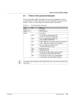
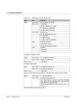
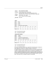
In the case of read access, the amount of data is based on the number of configured and
available devices. If, for example, k = 18 devices are configured, you will receive the
response m = 3+1 bytes.
The following is valid for bytes in position 5 and up:
Status and specification are the same:
–
Activated and connected: Write: "1“; Read: "1"
–
Not activated and not connected: Write: "0“; Read: "0"
Status and specification inconsistent:
–
Activated but not connected: Write: "1"; Read: „0“
–
Not activated but connected: Write "0"; Read: "1"
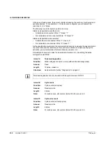
As the specification must match the connected terminals, by comparing the desired state in
the output data and the real status in the input data in addition to simply specifying the
activation, you can determine which terminals are present or not.
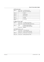
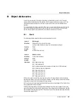
An example for access to index 7 is described in Section 4.3.3 „Specifying the active
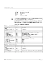
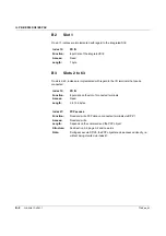
Index 12:
Terminal diagnostics
Function:
Station diagnostics byte 7 and up (without standard diagnostics)
Access:
Read
Length:
72 bytes, maximum
Structure:
As described in Section "Diagnostics" on page 2-1
Terminal diagnostics can only be used via the acyclic services of DP/V1.
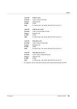
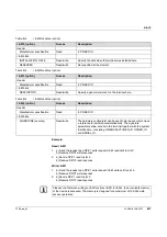
Index 20:
Cycle count
Function:
Cycle counter (all cycles)
Access:
Read and write
Length:
8 bytes
Note:
For write access, all counters (index 20 to 25) are set to 0
Index 21:
Cycle error count
Function:
Cycle counter (all faulty cycles)
Access:
Read and write
Length:
8 bytes
Note:
For write access, all counters (index 20 to 25) are set to 0
Содержание IL PB BK DI8 DO4/EF-PAC
Страница 2: ......
Страница 24: ...IL PB BK DI8 DO4 EF PAC 2 14 PHOENIX CONTACT 7725_en_01 ...
Страница 62: ...IL PB BK DI8 DO4 EF PAC 5 2 PHOENIX CONTACT 7725_en_01 ...
Страница 64: ...IL PB BK DI8 DO4 EF PAC 6 2 PHOENIX CONTACT 7725_en_01 ...
Страница 72: ...IL PB BK DI8 DO4 EF PAC A 8 PHOENIX CONTACT 7725_en_01 ...


