background image

Manual 

44 

7.4.3 

Collect data and align  
Proceed as in the horizontal machine alignment. Pay attention to the following differences:  


The minimal shaft rotation angle must not be smaller than 75° 

Corrective values for the parallel misalignment are irrelevant when it comes to cardan shafts and 
will not be displayed 

Standard tolerances cannot be used for cardan shafts. Please ignore them.  

Only  corrective  values  for  one  machine  base  are  needed,  because  parallel  misalignment  is  not 
corrected with cardan shafts.  

7.5 

Alignment of machine trains 

7.5.1 

Short explanation 

A machine train consists of three or more units with rotating shafts, which are connected with couplings, 
as  for  example  driving  unit 

– gear – driven unit. With a common alignment measurement, an alignment 

measurement  for  every  single  machine  would  be  necessary.  The  PCE-TU  3  system  performs  all 
necessary  measurements  automatically  and  offers  the  possibility  to  define  the  stationary  or  reference 
machine. To use this function, you should be familiar to 

chapter 7.1 (“Horizontal machine alignment”)

.  


7.5.2 

Execution of a machine train alignment 

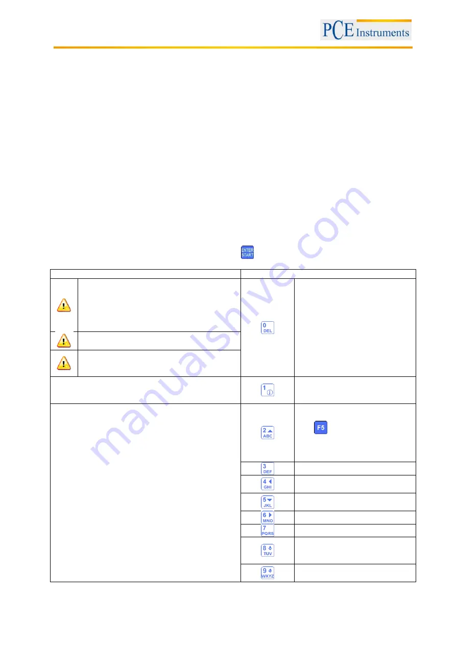
To start the program, select “machine train” and press  

. The main screen of the program will appear.  


What should be noted in this window 

Shortcuts in this window 


Similar to the horizontal alignment, a Soft 
Foot Measurement should be carried out 
before. If needed, corrections should be 
made. Do not forget to enter the dimensions 
in the menu for the horizontal machine 
alignment. 


Create a new train (initially 3 
units in the train) 


All needed dimensions should be entered 
correctly.  


The Sensor M must always be placed right to 
the coupling on the machine; also it is 
actually a stationary one.  

Functions in this window 


Dimensions of the machines and 
the selected coupling need to be 
entered first.  

Create/modify/view a train 


Determine parameters 


Enter dimensions 


Identify misalignment 


View the measured data 


Save the results 


Load saved results 


Collect data (refer to chapter 7.1 
„Horizontal machine alignment“) 

Use 

 in the measurement 

screen to finish the collection 
process and return to the main 
menu of the program 


View alignment results 


Add a machine on the left side of 
the train 


Add a machine on the right side 
of the train 


Set parameters 


reserved (no function) 


Save results to a file (see 

chapter 10 “Handling of the 
Data Dialogue window”


Load  data from file (see 

chapter 

10 

„Handling of the Data 

Содержание TU 3

Страница 1: ...ts UK Ltd Units 12 13 Southpoint Business Park Ensign way Hampshire Southampton United Kingdom SO31 4RF From outside UK 44 Tel 0 2380 98703 0 Fax 0 2380 98703 9 info pce instruments com www pce instru...

Страница 2: ...7 7 1 2 Change parameters 18 7 1 3 Data acquisition 19 7 1 4 Result 23 7 1 5 Live Alignment 24 7 2 Vertical machine alignment 28 7 2 1 Entry of machine dimension 29 7 2 2 Change add parameters 30 7 2...

Страница 3: ...re line programme 68 8 2 1 Short explanation 68 8 2 2 Main screen of the program configuration of planes and changing of parameters 68 8 2 3 Configuration process 69 8 2 4 Carry out measurement 70 8 2...

Страница 4: ...data transfer of the sensor 89 9 5 Set the user language 90 9 6 Set USB mode 91 10 Handling of the Data Dialogue window 92 11 My Documents option 94 11 1 Find organize folders and files 94 11 2 Save a...

Страница 5: ...rms they can be found in our general terms of business If you have any questions please contact PCE Instruments 2 1 Precautions The PCE TU 3 is a class II laser system with a typical wavelength of 670...

Страница 6: ...tion 0 01 or 0 001 mm Inclinometer Resolution 0 1 Interface USB Bluetooth Memory 2 GB Functions Horizontal alignment in every position from 60 to 360 Vertical alignment Auto sweep mode Adjustable tole...

Страница 7: ...lignment 3 Detector target 4 Exit hole of the laser beam 5 Horizontal alignment Front and top view of the measurement sensors 1 Reference point 2 Cable connector socket Measurement sensor side view 1...

Страница 8: ...centre lines of the shaft need to be concentric during normal operation 4 2 1 CE Conformity The Shaft alignment tool is conforming to the following CE requirements 2006 95 EC EN 61010 1 2001 EN 60825...

Страница 9: ...n and efficiency with the machine operator After that you need to determine the arrangement of correction planes Stationary machines S The position of the machine is not changed in the course of measu...

Страница 10: ...ows machine S from the point of view of machine M from 12 o clock position The surfaces of the measurement sensors are marked as S and M and should be mounted to the corresponding shaft of the machine...

Страница 11: ...an the surface of the laser detector and the exit hole of the sensor if necessary Use a cotton pad soaked in alcohol for the cleaning Do not use solvents for the cleaning under any circumstances Check...

Страница 12: ...e 2 Sensor S 3 Sensor M 4 Moveable machine F1 Front machine base F2 Rear machine base S M distance between the measurement sensors S C distance between sensor S and the middle of the coupling S F1 dis...

Страница 13: ...al alignment 1 Moveable machine 2 Stationary machine S M distance between the measurement sensors S C distance between sensor S and the middle of the coupling S F1 distance between sensor S and the al...

Страница 14: ...o middle of the detector 4 Alignment of the moveable machine M in order to make sure the laser beams meet S and M in the middle Rotate the shaft with the measurement sensors to the 9 00 position Aim t...

Страница 15: ...data entry main screens of programs and some other 6 2 Starting the PCE TU 3 Having completed the booting the main menu appears on the display To select a menu item press if the battery indication is...

Страница 16: ...le with the Bluetooth adaptor kit What should be noted in this window Shortcuts in this window Firstly carry out the Soft Foot Measurement to avoid unexpected errors during the alignment check the res...

Страница 17: ...indow Navigate down Enter distance sensor S middle of the coupling Enter distance sensor S sensor M Enter distance sensor S middle of the coupling Enter distance sensor S front machine base Enter dist...

Страница 18: ...s in this window Activate deactivate manual angle entry Manual entry or use of the sensor data Manual angle entry or data from integrated inclinometer Selection between 2 or 3 decimal digits Selection...

Страница 19: ...on twice to reverse sign Select the measurement unit mm or inch Set parallel misalignment Offset Save all data in one file see chapter 10 Handling of the Data Dialogue window Load data from file see c...

Страница 20: ...llow indictaion means that the rotation angle is over 60 A green indication means that the rotation angle is over the recommended area over 90 This symbol means that an expanded Y value range is used...

Страница 21: ...tector opening figure front and top view of the sensor side view of the sensor If the laser beams aim both detectors open the covers The X Y coordinates and the position von S and M are now displayed...

Страница 22: ...phase Adjust the laser beam until the value becomes 0 and wait for 5 seconds Push to save the Offset value After you have left the Offset menu the symbol appears to display the Offset settings Select...

Страница 23: ...r the angle afterwards If the cursor is in the first place of an entry field push the button twice to reverse sign Entry of thermal growth Selection of the measurement unit mm mils Interrupt continue...

Страница 24: ...hould be enabled for the required plane indicated by a blinking checkbox in the plane headline Loosen the machine bases now and start the adjustment with the help of the calculated corrective values 7...

Страница 25: ...9 00 position the position indication changes with the note for the second step e g 6 00 12 00 position After the second step is finished as well the note and the yellow dial vanish and the Live Alig...

Страница 26: ...ment extension Enter vertical parallel misalignment extension Enter vertical angular misalignment extension Navigate up through the entry fields Navigate down through the entry fields If the cursor is...

Страница 27: ...base F1 Entry of the thickness of the rear machine base F2 Remaining misalignment Navigate up through the entry fields Navigate down through the entry fields Save and exit Measurement unit Horizontal...

Страница 28: ...luetooth interface only with optional Bluetooth adaptor What should be noticed in this window Shortcuts in this window Check the result after the alignment by measurement again Determine new data Func...

Страница 29: ...ent results the following must be respected S C S F1 S F2 Navigate up through the entry fields Functions in this window Navigate down through the entry fields Enter distance sensor S middle of the cou...

Страница 30: ...digits Manual entry or use of the sensor data Selection between 2 or 3 decimal digits Selection of the measurement unit mm inch Alignment to the X and Y coordinates simultaneously or just to the Y coo...

Страница 31: ...tion entry if activated Selection of measurement unit mm inch Navigate through collected data Delete add replace measured values Restart all values are deleted Set Offset Enter Ym values if manual ent...

Страница 32: ...n be deleted or replaced If this sign is not displayed in the window the current value has not been saved yet Pressing you can store the value The absence of the laser beam position indicator and a re...

Страница 33: ...ationary and moveable side Manual angle Note Box Dial with measurement points and the graphically displayed angles Entire rotation angle needs to be larger than 60 Laser beam position indication Seria...

Страница 34: ...r the other to the middle of the detector opening figure front and top view of the sensor side view of the sensor If the laser beams aim both detectors open the covers The X Y coordinates and the posi...

Страница 35: ...d phase Adjust the laser beam until the value gets 0 and wait for 5 seconds Push to save the Offset value After you have left the Offset menu the symbol appears to display the Offset settings Select f...

Страница 36: ...and enter the angle afterwards If the cursor is in the first place of an entry field push the button twice to reverse sign Entry of thermal growth Selection of the measurement unit mm mils Pause cont...

Страница 37: ...nt with the help of the calculated corrective values in the 9 3 plane 6 12 plane Live Alignment To start the 6 12 plane Live Alignment the sensors should be located in the 6 or 12 o clock position If...

Страница 38: ...o close the window press once again Before you continue working after the position of the sensors was changed you need to place the sensors in two predefined positions Proceed as described in 7 1 5 4...

Страница 39: ...olerances via RPM rotations per minute Manual entry of tolerances If the RPM selection is activated Raise RPM by one step If manual entry is activated Select parallel misalignment If RPM selection is...

Страница 40: ...e feet Save results to a file see chapter 10 Handling of the Data Dialogue window Firstly enter the machine dimensions just as described with the horizontal alignment or skip the process by pressing a...

Страница 41: ...refore please do refer to chapters 7 1 Horizontal machine alignment and 5 5 Rough alignment The differences to these chapters are described in the following Drive Shaft main menu What should be noted...

Страница 42: ...indow Shortcuts in this window Enter distance sensor S sensor M Enter distance front machine base rear machine base Navigate up Navigate down Switch between measurement units mm mils Save and exit Mac...

Страница 43: ...e manual data entry Functions in this window Activate deactivate manual angle entry Manual entry or use of the sensor data Manual angle entry Selection between 2 or 3 decimal digits Selection between...

Страница 44: ...gnment To start the program select machine train and press The main screen of the program will appear What should be noted in this window Shortcuts in this window Similar to the horizontal alignment a...

Страница 45: ...or to scroll through the complete train press to enter the dimensions for the machine of the current coupling Press to change the parameters see chapter 7 1 2 Change parameters press to determine misa...

Страница 46: ...th are always valid for the left shaft or machine Zoom in Zoom out Define the current machine as reference machine Save results to a file see chapter 10 Handling of the Data Dialogue window Open pop u...

Страница 47: ...art the Spindle Program select Spindle in the main menu and press The main screen of the Spindle Program will appear Current machine Current machine number Machine which is currently selected as stati...

Страница 48: ...Mark two points on the machine bed near and far where the receiver shall be placed on the tool slide for future measurement Enter the distance between the near and the far measurement point Mount the...

Страница 49: ...nment of a spindle are available after all four measurements were carried out To leave the current screen press To leave the Spindle Program press again To save the results press refer to chapter 10 H...

Страница 50: ...ieve results which are as accurate as possible you should carry out alignment very carefully due to planes Plan your measurement placing the transmitter in the first position 12 o clock and confirm th...

Страница 51: ...l shafts Functions in this window Enter amount of measurement points positions Create modify view points Change parameters Enter dimensions Start measurement View results available if all required mea...

Страница 52: ...distance to the next point Repeat the process until all distances are entered To change parameters press The parameter screen will appear To activate or deactivate the manual data entry press To acti...

Страница 53: ...ng data if activated Manually entering of the receiver value H Manually entering of the angle necessary for the position confirmation Switch between measurement units Open context menu Carry out or re...

Страница 54: ...int number 1 and reference point number 2 Press to confirm In order to delete a reference point enter as the value Best Fit Mode in this mode the result is the difference between the calculated best f...

Страница 55: ...rry out measurement Manual data entry if activated Switch between table and graph illustration Define reference point use to confirm your entry Switch reference point mode Save Repeat measurement all...

Страница 56: ...Manual 56 Ref Point Mode Best Fit Mode Red indicates that tolerance is exceeded...

Страница 57: ...e points where the receiver shall be placed Align the laser towards X and Y direction within 0 5 mm and start the Flatness Program Use the S or M sensor as a receiver The receiver should be placed wit...

Страница 58: ...alue for averaging and confirm with To get to the Auto Router settings press Press to save and leave the screen 8 1 3 1 Auto Router The Auto Router can be deactivated or configured in the two followin...

Страница 59: ...to enter a value for the total width length or line column spacing Every time you change the total width length the values for the line column spacing are recalculated and vice versa The grid is defi...

Страница 60: ...d to be entered Change the line ring position of the line ring which the selected point belongs to Functions in this window Change the position of the column which the selected point belongs to Change...

Страница 61: ...ote Zahl bedeutet dass mehr Zeilen Spalten existieren und per Scrolling abgerufen werden k nnen Line position Selected point Column position Change line position Change column position Add line bottom...

Страница 62: ...re ready before carrying out another measurement sandglass symbol must not be blinking Delete selected point Functions in this window View result Carry out measurement at the selected point Delete the...

Страница 63: ...olumn Receiver X axis value Laser beam position indicator Selected point Blinking symbol means that laser beam is out of aim Measured point Empty point Receiver Y axis value Inclinometer Sensor temper...

Страница 64: ...11 Reference modes There are three reference modes you can select between by pressing 8 1 11 1 No reference plane The result is an unchanged receiver value 8 1 11 2 Laser Plane If no reference points...

Страница 65: ...s in the Laser Plane mode 8 1 13 Result modes There are three different modes to view the results Original Values are shown as positive and negative values All positive Values are shown relative to th...

Страница 66: ...lue Peak Peak peak to peak value Average average value Std deviation standard deviation value Tolerance tolerance value The coloured bar on the bottom of the screen shows error percentages and the amo...

Страница 67: ...Manual 67 2 points in the positive over reference red range 3 points in the negative under reference yellow range...

Страница 68: ...Shortcuts in this window The required dimensions should be entered correctly can be changed later on if recommended measurement data will not be influenced Start a new measurement Functions in this wi...

Страница 69: ...er for the particular plane To do that press and enter the particular value for the current plane If you want to change parameters press to get to the parameter screen Here you can activate deactivate...

Страница 70: ...or serial the connection establishment can take between 2 and 30 40 seconds It is recommended to wait about 10 seconds cable connection or about 50 seconds wireless connection If no connection is esta...

Страница 71: ...ried out to calculate the result Save as many measurements as possible max 36 in order to receive a result as accurate as possible The minimum rotation angle amount of the particular rotations between...

Страница 72: ...Press to save In order to delete the reference points enter the value Best Fit Mode In this mode the result is the difference between the calculated best fit reference line and the detector value The...

Страница 73: ...he component towards zero with the help of the measurement values on the screen To stop the Live Mode and to receive the result after the movement press Do not stop the Live Mode if the measurement va...

Страница 74: ...data will not be influenced Start a new measurement Functions in this screen Enter number of measurement points positions Create modify view point Create modify view Part Splice Change parameter Ente...

Страница 75: ...cessary to carry out a straightness measurement of the whole object correctly If the effective length of the laser is longer than the measured object there is no need to use parts splices Overlap poin...

Страница 76: ...ss to reach the parameter screen Here you can activate deactivate the manual data entry by pressing or the manual angle entry by pressing Pressing makes it possible to switch between the measurement u...

Страница 77: ...to the receiver with the help of the adjustment screws on the transmitter once again The laser beam should aim the middle of the receiver again Move the receiver to the first measurement point Be sur...

Страница 78: ...e line and the receiver value To define reference points press and enter reference point number 1 and reference point number 2 Press to confirm In order to delete a reference point enter as the value...

Страница 79: ...o return to the main screen Number of the calculated points including overlap points distance Overlap points Point number and splice number Splice number is only displayed when splices are used Yellow...

Страница 80: ...t 1 to Point 5 Move the transmitter to its next position Yellow Square Carry out rough laser alignment for the second splice Note Point 1 on the second splice has the same physical position on the obj...

Страница 81: ...ceive on the selected position press and after that to start the Live Mode for the next selected plane The alignment of a point can influence other points Repeat the measurements after using the Live...

Страница 82: ...be noted in this window Shortcuts in this window All required dimensions should be entered correctly can be changed later on if recommended Start new measurement or repeat measurement all collected da...

Страница 83: ...wards Carry out measurements for Point 3 and Point 4 now The RL 20 laser transmitter must not be moved after the beginning of the measurement Be careful when you turn the laser beam The order of measu...

Страница 84: ...e results press To return to the main screen of the program press If you want to enter tolerances press If the calculated results are out of your tolerance range the vertical plane is illustrated incl...

Страница 85: ...ieve firmware version and status information Set language Set USB mode Set date and time Configure automatic turn off View set up program licences Set data transfer to the sensor Set user language Set...

Страница 86: ...s in this window Shortcuts in this window Navigate left between the fields Navigate right between the fields Increase the current value Decrease the current value Move between the fields cyclically Le...

Страница 87: ...ow Setting of the turn off time in seconds Note 1 To deactivate auto turn off set the time to zero or leave the box blank Note 2 If the values below 30 seconds are entered the box is highlighted in ye...

Страница 88: ...esman If he sends you the license file copy it to the My documents folder on your instrument or to the SD card and insert it To load this file press and a loading dialog appears Use the arrow keys to...

Страница 89: ...etween Bluetooth and serial interface Configure Bluetooth interface Slave Device Number Select Bluetooth interface Select serial interface If Bluetooth is activated Use a sensor via Bluetooth Use both...

Страница 90: ...al 90 9 5 Set the user language To set the user language press Functions in this window Shortcuts in this window Change user language Navigate through available languages Save and exit Exit without sa...

Страница 91: ...Microsoft Active Sync 4 5 to get access to the device Do not start any loading or saving processes on the device while the device is used via USB in mass storage mode Functions in this window Shortcut...

Страница 92: ...options The My documents folder internal always available The Storage Card folder external SD card only available if an SD card is inserted General structure of the Data Dialogue window Folder and fi...

Страница 93: ...t is selected and you are at a subfolder Navigate a step up in the folder hierarchy If folder and file list is selected Delete the selected folder file Caution If folder and file list is selected Crea...

Страница 94: ...tcuts in this window Find folders and files Switch between internal storage and SD card Delete folders Delete files Create a new folder If the folder and file list is selected Navigate through the lis...

Страница 95: ...If the storage medium is selected Selection between SD card Storage Card and internal storage My documents Move up a step within the folder hierarchy If the folder or file list is selected Delete fil...

Страница 96: ...hese tolerances RPM Good Acceptable Parallel misalignment Angular misalignment Parallel misalignment Angular misalignment Up to 1000 0 08 0 07 0 12 0 10 Up to 2000 0 06 0 05 0 10 0 08 Up to 3000 0 04...

Страница 97: ...se them or give them to a recycling company which disposes of the devices in line with law If you have any questions please contact PCE Instruments 14 Contact If you have any questions about our range...

Страница 98: ...4 D 59872 Meschede Deutschland Tel 02903 976 99 0 Fax 02903 976 99 29 info pce instruments com www pce instruments com deutsch Bedienungsanleitung Lasermeter PCE TU 3 Version 1 1 Erstelldatum 06 11 2...

Страница 99: ...ndern 15 6 1 3 Daten sammeln 16 6 1 4 Ergebnis 19 6 2 Vertikale Maschinenausrichtung 24 6 2 1 Maschinenabmessungen eingeben 25 6 2 2 Parameter ndern hinzuf gen 25 6 2 3 Daten sammeln 26 6 2 4 Ergebni...

Страница 100: ...nd Parameter ndern 66 7 3 2 Messungen durchf hren 68 7 3 3 Ergebnisse betrachten und speichern 70 7 3 4 Tutorial zur Teilst ckbenutzung 72 7 3 5 Live Modus 72 7 4 Rechtwinkligkeitsprogramm Squareness...

Страница 101: ...it einer typischen Wellenl nge von 670 nm einer Leistung von 1 MW und einer maximalen Strahlungsenergie von 0 1 mJ pro Impuls Der Klasse II Laser erf llt die Anforderungen nach ANSI BS 4803 IEC 825 un...

Страница 102: ...2004 108 EC EN 61326 1 2006 EN 61326 2 2 2006 EN 55011 2009 A1 3 2 Technische Spezifikationen und Funktionen Sensortyp positionssensible Photodioden 10 x 10 mm Lasertyp sichtbar rot 635 670 nm 1 MW Ma...

Страница 103: ...fang Das PCE TU 3 Messsystem beinhaltet 1x PCE TU 3 Displayeinheit 2x Messsonden 2x Montage Sets f r die Messsonden 1x Ma band 1x Ladeger t 1x Anschlusskabel 1x Software CD ROM 1x USB Kabel 1x Bedienu...

Страница 104: ...hrer ob eine Umpositionierung der beweglichen Maschine M m glich und unter Bedienungs und Effektivit tsgesichtspunkten sinnvoll ist und bestimmen Sie dann die Anordnung der Korrekturebenen Station re...

Страница 105: ...ustieren Sie die Position der Maschinenf e an der beweglichen Maschine anhand der ermittelten Korrekturwerte auf dem Display Achtung F r die Durchf hrung der Messung ist es wichtig sich an der Rotatio...

Страница 106: ...usreichend 4 2 Einrichtung des Ger tes Bevor Sie mit dem Ger t arbeiten kontrollieren Sie den Batteriestatus und laden Sie die Batterie falls n tig Der Batteriestatus wird als kleines farbiges Bild un...

Страница 107: ...wischen den Messsensoren S C Abstand zwischen Sensor S und Mitte der Kupplung S F1 Abstand zwischen Sensor S und Maschinenfu F1 S F2 Abstand zwischen Sensor S und Maschinenfu F2 muss gr er sein als S...

Страница 108: ...Bild 8 Drehen Sie die Welle mit den Messsensoren in die 9 Uhr Position Zielen Sie mit den Lasern auf die Mitte der geschlossenen Detektor ffnung Drehen Sie die Welle mit den Messsensoren auf die 3 Uh...

Страница 109: ...rammen und einige andere 5 2 Das PCE TU 3 starten Nach dem Hochfahren erscheint das Hauptmen auf dem Display Im Hauptmen W hlen sie einen Men punkt und dr cken Sie Wenn die Batterieanzeige unten im Di...

Страница 110: ...it optionalem Bluetooth Adapter Kit Zu beachten in diesem Bildschirm Shortcuts in diesem Bildschirm F hren Sie zun chst eine Kippfu Messung Soft Foot durch um unerwartete Fehler w hrend der Ausrichtun...

Страница 111: ...1 S F2 Navigieren nach oben Funktionen in diesem Bildschirm Navigieren nach unten Strecke Sensor S Kupplungsmitte eingeben Strecke Sensor S Sensor M eingeben Strecke Sensor S vorderer Maschinenfu eing...

Страница 112: ...eingabe aktivieren deaktivieren Manuelle Eingabe oder Verwendung der Sensordaten Manuelle Winkeleingabe oder Daten aus integriertem Neigungssensor Auswahl zwischen 2 oder 3 Nachkommastellen Auswahl zw...

Страница 113: ...e Eingabe aktiviert ist Winkel eingeben wenn manuelle Winkeleingabe aktiviert ist Wenn der Cursor sich an erster Stelle in einem Eingabefeld befindet dr cken Sie die Taste zweimal um ein negatives Vor...

Страница 114: ...zu klein ist geringer als 6 Eine hellrote Anzeige bedeutet dass der Rotationswinkel aus den Winkeln der einzelnen Messpunkte nicht den Anforderungen gen gt mindestens 60 Eine gelbe Anzeige bedeutet d...

Страница 115: ...etektorabdeckungen auszurichten Bild 1a b Wenn die Laserstrahlen auf beiden Empf ngern zentriert sind ffnen Sie die Abdeckungen Auf dem Bildschirm werden nun die X Y Koordinaten und die Position f r b...

Страница 116: ...en Funktionen in diesem Bildschirm Distanzscheiben Simulation Beobachten des berechneten Versatzes Live Ausrichtung durchf hren Live Ausrichtung pausieren weiterf hren Manuelle Winkeleingabe falls akt...

Страница 117: ...e Ausrichtung benutzt werden kann Sonst ist dies f r die jeweilige Ebene nicht m glich Diese blinkende Fehlermeldung bedeutet dass die Position der Wellen unerwartet ver ndert wurde Die Live Ausrichtu...

Страница 118: ...Ausrichtung ab nur dass hier die Sensoren nicht in eine vordefinierte Position gebracht werden m ssen Es ist jedoch empfehlenswert die Sensoren ca in einem Winkel von 45 zu positionieren 45 135 225 31...

Страница 119: ...anzen ber die RPM Umdrehungen pro Minute festlegen Manuelle Eingabe von Toleranzen Wenn RPM Auswahl aktiviert ist RPM um einen Schritt erh hen Wenn Manuelle Eingabe aktiviert ist Parallelversatz Einga...

Страница 120: ...r Stelle in einem Eingabefeld befindet dr cken Sie die Taste zweimal um ein negatives Vorzeichen einzugeben Speichern und verlassen 6 1 4 3 Distanzscheiben Simulation Um Distanzscheiben zu simulieren...

Страница 121: ...Zu beachten in diesen Bildschirm Shortcuts in diesem Bildschirm Kontrollieren Sie nach der Ausrichtung das Resultat indem Sie eine weitere Messung vornehmen Neue Daten ermitteln Funktionen in diesem...

Страница 122: ...zuf gen dr cken Sie Zu beachten in diesem Bildschirm Shortcuts in diesem Bildschirm Benutzen Sie die biaxial live Funktion nur bei stabilen Wellenpositionen da schon kleinste Drehungen zu Fehlern f hr...

Страница 123: ...gabe von Ys und Ym Werten wenn aktiviert Manuelle Neigungseingabe Auswahl der Ma einheit mm Zoll Durch gesammelte Daten navigieren Messwerte l schen erg nzen ersetzen Von vorne beginnen alle Werte l s...

Страница 124: ...ert kann bei Bedarf gel scht oder ersetzt werden Ist dieses Symbol nicht zu sehen hei t das dass der aktuelle Wert noch nicht gespeichert wurde Durch Dr cken von k nnen Sie den Wert speichern Das Fehl...

Страница 125: ...et dass die Daten nicht gut aber akzeptabel sind Ein roter Punkt bedeutet dass die Daten schlecht sind Diese Messung muss gel scht oder wiederholt werden Wenn Sie eine geringe Anzahl von Messpunkten v...

Страница 126: ...it dem Ausrichten zu beginnen 6 2 3 1 Einstellen des Parallelversatzes Dr cken Sie um den Parallelversatz einzustellen Zu beachten in diesem Bildschirm Shortcuts in diesem Bildschirm Drehen Sie nicht...

Страница 127: ...ellen Auswahl der Ma einheit mm Zoll Eingabe von Toleranzen Flanschbolzen Korrekturwerte ansehen mit Live Update Ergebnisse der Ausrichtung speichern Ergebnisse der Ausrichtung laden Zur Flansch Bolze...

Страница 128: ...ie laterale Position der bewegbaren Maschine 9 3 Ebene Live Ausrichtung Um die 9 3 Ebene Live Ausrichtung zu starten sollten sich die Sensoren in der 9 oder 3 Uhr Position befinden Wenn Sie die Wellen...

Страница 129: ...n gebracht werden m ssen Es ist jedoch empfehlenswert die Sensoren ca in einem Winkel von 45 zu positionieren 45 135 225 315 um Messfehler zu vermeiden 6 2 4 1 Bolzen Korrekturwerte ansehen Um die Kor...

Страница 130: ...anzen ber die RPM Umdrehungen pro Minute festlegen Manuelle Eingabe von Toleranzen Wenn RPM Auswahl aktiviert ist RPM um einen Schritt erh hen Wenn Manuelle Eingabe aktiviert ist Parallelversatz Einga...

Страница 131: ...er horizontalen Ausrichtung oder berspringen Sie diesen Vorgang indem Sie dr cken und gehen Sie zum Sensor Ziel Bildschirm Wenn die Laserstrahlen ausgerichtet sind und Sie den Sensor Ziel Bildschirm v...

Страница 132: ...rschiede zu diesen Kapiteln werden im Folgenden beschrieben Gelenkwellen Hauptmen Zu beachten in diesem Bildschirm Shortcuts in diesem Bildschirm Vor der Messung sollte eine Kippfu messung durchgef hr...

Страница 133: ...cuts in diesem Bildschirm Strecke Sensor S Sensor M eingeben Strecke vorderer Maschinenfu hinterer Maschinenfu eingeben Zwischen den Eingabefeldern nach oben navigieren Zwischen den Eingabefeldern nac...

Страница 134: ...leingabe aktivieren deaktivieren Manuelle Eingabe oder Benutzung der Sensordaten Manuelle Winkeleingabe oder Daten aus integriertem Neigungssensor Auswahl zwischen 2 oder 3 Nachkommastellen Auswahl zw...

Страница 135: ...maschine festzulegen Um diese Funktion zu nutzen sollten Sie mit dem Ablauf der horizontalen Maschinenausrichtung Kapitel 6 1 vertraut sein Durchf hren einer Maschinenzug Ausrichtung Um das Programm z...

Страница 136: ...len Kupplung bedeutet dass die Abmessungen korrekt eingegeben wurden und Daten korrekt ermittelt wurden Dr cken Sie oder um durch den kompletten Zug zu scrollen dr cken Sie um die Abmessungen f r die...

Страница 137: ...nd immer f r die linke Welle bzw Maschine g ltig Heranzoomen Herauszoomen Aktuelle Maschine als Referenzmaschine festlegen Ergebnisse in Datei abspeichern siehe Kapitel 9 Umgang mit Datei Dialogfenste...

Страница 138: ...n diesem Bildschirm Anzahl der Messpunkte Positionen eingeben Abmessungen eintragen Messung starten Messergebnisse betrachten verf gbar wenn alle ben tigten Messungen abgeschlossen sind Speichern Abst...

Страница 139: ...u verlassen dr cken Sie Um das Spindel Programm zu verlassen dr cken Sie anschlie end erneut Um die Ergebnisse zu speichern dr cken Sie siehe Kapitel 9 Umgang mit Datei Dialogfenstern Etikettenpositio...

Страница 140: ...zu erhalten sollten Sie die Ausrichtung sehr vorsichtig durchf hren mit Hilfe von Libellen Planen Sie die Messung indem Sie den Sender in der ersten Position 12 Uhr platzieren best tigen Sie die Posi...

Страница 141: ...Bildschirm Anzahl der Messpunkte Positionen eingeben Punkte erstellen modifizieren betrachten Parameter ndern Abmessungen eintragen Messung starten Ergebnisse betrachten verf gbar wenn alle ben tigte...

Страница 142: ...e end um den Abstand zum n chsten Punkt einzutragen Wiederholen Sie diesen Vorgang bis alle Abst nde eingetragen sind Um Parameter zu ndern dr cken Sie Es erscheint der Parameterbildschirm Zum Ein ode...

Страница 143: ...tiviert Manuelle Eingabe des Empf ngerwerts H Manuelle Winkeleingabe ben tigt zur Positionsbest tigung Umschalten zwischen den Ma einheiten Kontextmen ffnen Messung durchf hren oder ersetzen Vorw rts...

Страница 144: ...nzpunktnummer 2 ein Dr cken Sie nun zum Best tigen Um einen Referenzpunkt zu l schen geben Sie als Wert ein Best fit Modus In diesem Modus ist das Ergebnis die Differenz aus der berechneten geeignetes...

Страница 145: ...alls aktiviert Zwischen Tabellen und Graphansicht umschalten Referenzpunkt definieren benutzen Sie um die Eingabe zu best tigen Referenzpunktmodus umschalten Speichern Messung wiederholen alle aktuell...

Страница 146: ...BETRIEBSANLEITUNG 49 Ref points Modus Best fit Modus Rot bedeutet Toleranz berschreitung...

Страница 147: ...ie die Punkte an denen der Empf nger positioniert werden soll Richten Sie den Laser in X und Y Richtung innerhalb von 0 5 mm aus und starten Sie das Ebenheits Programm Benutzen Sie den S oder M Sensor...

Страница 148: ...den Auto Router Einstellungen zu gelangen dr cken Sie Dr cken Sie zum Speichern und Verlassen dieses Bildschirms Auto Router Der Auto Router kann deaktiviert oder in den zwei folgenden Modi konfigurie...

Страница 149: ...mgekehrt Das Gitter wird mit gleichbleibenden Zeilen bzw Spaltenabst nden definiert Einzelne Abst nde k nnen sp ter aber noch unabh ngig voneinander ge ndert werden Dr cken Sie um zu speichern und zum...

Страница 150: ...gen Zeile wird an der Unterseite eingef gt Ring als u erer Ring Zeile Ring zu der dem der ausgew hlte Punkt geh rt l schen Spalte Punkt einf gen Spalte wird auf der rechten Seite eingef gt Punkt im U...

Страница 151: ...e Daten bereit sind bevor Sie die n chste Messung durchf hren Sanduhr Symbol darf nicht blinken Gew hlten Punkt l schen Funktionen in diesem Bildschirm Ergebnis betrachten Messung an gew hltem Punkt d...

Страница 152: ...Achsen Wert Laserstrahl Positionsindikator Gew hlter Punkt Blinkendes Symbol Laserstrahl au erhalb des Ziels Gemessener Punkt Leerer Punkt Empf nger Y Achsen Wert Sensor Neigung Sensor Temperatur Pun...

Страница 153: ...renzebenen Modi Es gibt drei Referenzebenen Modi zwischen denen Sie mit umschalten k nnen Keine Referenzebene No reference plane Das Ergebnis ist der unver nderte Empf ngerwert Laser Referenzebene Las...

Страница 154: ...Ergebnis Modi Es gibt drei Ergebnis Modi zwischen denen Sie mit umschalten k nnen Original Werte werden als positive und negative Werte angezeigt All positive Werte werden relativ zum niedrigsten Wer...

Страница 155: ...ert an Minimum Zeigt Minimalwert an Peak Peak Zeigt den Spitze Spitze Wert an Average Zeigt den Durchschnittswert an Std deviation Zeigt die Standardabweichung vom Durchschnittswert an Tolerance Zeigt...

Страница 156: ...ogramm zu starten w hlen Sie Loch Mittelachse im Hauptmen unter dem Punkt Geometrie und dr cken Sie Es erscheint der Hauptbildschirm des Programms 7 2 1 Hauptbildschirm des Programms Ebenen konfigurie...

Страница 157: ...onfiguration Geben Sie die Anzahl der Ebenen L cher ein indem Sie dr cken und den Wert im Eingabefeld eingeben der Wert sollte zwischen 3 und 300 liegen Sind die zu messenden Ebenen in gleichen Abst n...

Страница 158: ...er verwenden m chten Zur Durchschnittswertbildung dr cken Sie geben Sie eine Probenanzahl ein und best tigen Sie mit Dr cken Sie zum Speichern und Verlassen des Parametermen s 7 2 2 Messungen durchf h...

Страница 159: ...n Sie eine Weile Keine Verbindung zu den Sensoren Aktuelle Messpunktnummer Ein bedeutet keine Messung Detektorwert bedeutet keine Daten Empf ngerneigung in Grad bedeutet keine Daten Gespeicherte Messp...

Страница 160: ...ebnis zu berechnen Speichern Sie so viele Messungen wie m glich bis zu 36 um ein m glichst genaues Ergebnis zu erhalten Der minimale Gesamtdrehwinkel Summe der einzelnen Drehungen zwischen den einzeln...

Страница 161: ...ein Dr cken Sie zum Speichern Um die Referenzpunkte zu l schen geben Sie als Wert ein Best fit Modus Im diesem Modus ist das Ergebnis die Differenz aus der berechneten Best fit Referenzlinie und dem...

Страница 162: ...te auf dem Bildschirm Um den Live Modus zu stoppen und das Ergebnis nach dem Bewegen zu erhalten dr cken Sie Stoppen Sie den Live Modus nicht w hrend die Messdaten nicht bereit sind Laserstrahl au erh...

Страница 163: ...Neue Messung starten Funktionen in diesem Bildschirm Anzahl der Messpunkte Positionen eingeben Punkt erstellen modifizieren betrachten Teilst ck Splice erstellen modifizieren betrachten Parameter nder...

Страница 164: ...Geradlinigkeitsmessung des ganzen Objektes korrekt durchf hren zu k nnen Wenn die Nutzl nge des Lasers l nger als das zu messende Objekt ist kann auf die Verwendung von Teilst cken Splices verzichtet...

Страница 165: ...ter ndern wollen dr cken Sie um in den Parameterbildschirm zu gelangen Hier k nnen Sie die manuelle Dateneingabe mit Druck auf oder die manuelle Winkeleingabe mit Druck auf aktivieren deaktivieren Dur...

Страница 166: ...erstrahls auf dem Empf nger mit Hilfe der Justierschrauben am Transmitter Der Laserstrahl sollte wieder mittig auf das Ziel auf dem Empf nger treffen Bewegen Sie jetzt den Empf nger zum ersten Messpun...

Страница 167: ...die Differenz zwischen der kalkulierten Referenzlinie und dem Empf ngerwert Um Referenzpunkte zu definieren dr cken Sie und geben Sie dann Referenzpunktnummer 1 und Referenzpunktnummer 2 ein Dr cken S...

Страница 168: ...um zum Hauptbildschirm zur ckzukehren Anzahl der berechneten Punkte einschlie lich berlappungspunkte Distanz berlappungspunkte Punktnummer und Teilst cknummer Teilst cknummer wird nur bei Verwendung...

Страница 169: ...e Ausrichtung f r das zweite Teilst ck durch Beachten Sie Folgendes Punkt 1 auf dem zweiten Teilst ck hat dieselbe physische Position auf dem Objekt wie Punkt 4 auf dem ersten Teilst ck Punkt 2 auf de...

Страница 170: ...dus f r die neu gew hlte Ebene zu starten Das Ausrichten eines Punktes kann sich auf andere Punkte auswirken Wiederholen Sie also die Messungen nach dem Benutzen des Live Modus gehen Sie zum Ergebnis...

Страница 171: ...Bildschirm Shortcuts in diesem Bildschirm Die ben tigten Abmessungen sollten korrekt eingetragen sein sie k nnen sp ter bei Bedarf noch ge ndert werden Neue Messung beginnen bzw Messung wiederholen a...

Страница 172: ...um 90 in Richtung der zweiten Fl che F hren Sie nun Messungen f r die Punkte 3 und 4 durch Der RL 20 Lasersender darf nicht bewegt werden nachdem die Messung begonnen wurde Seien Sie vorsichtig bei de...

Страница 173: ...ezeigt Systemeinstellungen 8 Funktionen in diesem Bildschirm Shortcuts in diesem Bildschirm Datum und Uhrzeit einstellen Automatische Abschaltung konfigurieren Programmlizenzen ansehen einrichten Eins...

Страница 174: ...en den Feldern nach rechts bewegen Aktuellen Wert erh hen Aktuellen Wert verringern Zwischen den Feldern nach links bewegen zyklisch Datum und Uhrzeiteinstellungen verlassen Fenster schlie en Sensor S...

Страница 175: ...dschirm Einstellen der Abschaltzeit in Sekunden Hinweis 1 Um die automatische Abschaltung zu deaktivieren setzen Sie diese auf null oder lassen Sie das Eingabefeld leer Hinweis 2 Wenn Werte unter 30 S...

Страница 176: ...dieser Ihnen die Lizenzdatei zusendet kopieren Sie diese in den My documents Ordner auf dem Ger t oder auf die SD Karte und setzen Sie diese ein Um die Datei zu laden dr cken Sie und ein Ladedialog er...

Страница 177: ...lle ausw hlen Wenn Bluetooth aktiviert ist Einen Sensor ber Bluetooth verwenden Beide Sensoren ber Bluetooth verwenden Klasse des Bluetooth Slave Ger tes ndern so lassen COD ver ndern Sie diese nicht...

Страница 178: ...en tigt um auf das Ger t zugreifen zu k nnen F hren Sie keine Lade oder Speichervorg nge auf dem Ger t durch w hrend auf das Ger t per USB im Massenspeicher Modus zugegriffen wird Funktionen in diesem...

Страница 179: ...Der My Documents Ordner intern immer vorhanden Der Storage Card Ordner externe SD Karte nur vorhanden wenn eine SD Karte eingelegt ist Genereller Aufbau des Datei Dialogfensters Ordner und Dateiliste...

Страница 180: ...d Sie sich in einem Unterordner befinden bewegen Sie sich eine Stufe in der Ordnerhierarchie nach oben Wenn die Ordner und Dateiliste ausgew hlt ist L schen des Ordners der Datei Vorsicht Wenn die Ord...

Страница 181: ...Dateien l schen Neue Ordner erstellen Wenn die Ordner und Dateiliste ausgew hlt ist Durch die Liste navigieren Wenn das Speichermedium Auswahlfeld ausgew hlt ist Auswahl zwischen SD Karde Storage Card...

Страница 182: ...tufe nach oben bewegen Wenn die Ordner und Dateiliste ausgew hlt ist Datei oder Ordner l schen Wenn Ordner und Dateiliste ausgew hlt ist neuen Ordner erstellen Zwischen der Ordner und Dateiliste dem S...

Страница 183: ...Winkelversatz Parallelversatz Winkelversatz Bis 1000 0 08 0 07 0 12 0 10 Bis 2000 0 06 0 05 0 10 0 08 Bis 3000 0 04 0 04 0 07 0 07 Bis 4000 0 03 0 03 0 05 0 05 Mehr als 4000 0 02 0 02 0 04 0 04 Datein...

Страница 184: ...V PCE Deutschland GmbH Im Langel 4 59872 Meschede Zur Umsetzung der ElektroG R cknahme und Entsorgung von Elektro und Elektronikaltger ten nehmen wir unsere Ger te zur ck Sie werden entweder bei uns w...

Отзывы: