Parker PHM Скачать руководство пользователя страница 29

Chapter 4: Maintaining the Monitor

Performing Internal Maintenance


PHM/PM User Guide


4-4

cables from the end located on both the backshell boards.


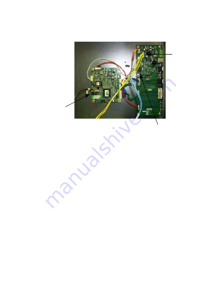
Figure 4-2: Accessing the Internal Cables of the Monitor

10

Once the cables are disconnected, gently lift the backshell off the 

unit. 

11

Proceed to the specific maintenance or troubleshooting procedures 

you need to perform. 

Closing the Backshell

1

Carefully connect the touchscreen, display and inverter board cables 

to their respective connectors (see Figure 4-2). Be sure you orient 

the cables so that you do not bend their pins.

2

Secure the backshell to the unit using the retaining screws or nuts 

removed earlier. There are 12 retaining screws on 15" units and 16 

retaining nuts on 17" units.

3

Reinstall the unit in its enclosure or on its arm.

4

Reattach the power input cable, touchscreen cable, video input cable 

and the ground cable at the left side of the monitor.

5

Reconnect the monitor to a power source.

6

Turn on the computer and the monitor.

Display cable

Touchscreen cable

Inverter
cable

Содержание PHM

Страница 1: ...PHM PM User Guide April 2009 Parker Hannifin Electromechanical Automation Division 50 W TechneCenter Drive Milford Ohio 45150 Part A3 06717 02...

Страница 2: ...r s standard product warranty covers this item for 24 months from the date of shipment from Parker Exceptions appear below Flat panel display backlight bulbs have a 90 day warranty Third party product...

Страница 3: ...s 2 2 Electrical Guidelines 2 2 Field Terminal Wiring Requirements 2 3 Enclosure Guidelines 2 3 Radiated Emissions Guidelines 2 3 Accessing Ports and Other Controls 2 4 Mounting the Monitor in an Encl...

Страница 4: ...2 Opening the Back Cover 4 3 Closing the Backshell 4 4 Replacing a Fuse 4 5 Resolving Common Problems 4 6 Problems with Display Operation 4 6 Problems with the Displayed Image 4 7 A Monitor Specificat...

Страница 5: ...apter 2 Installing the Monitor Explains how to select an appropriate location for the monitor and how to install the monitor in a control enclosure Chapter 3 Connecting to a Computer Explains how to c...

Страница 6: ...eyboard keys that must be pressed simultaneously For example Ctrl Alt Delete Note Alternative approaches or issues you should be aware of while using a particular function Important Information that w...

Страница 7: ...s original equipment manufacturers OEM system integrators or distributors If you have a question about the monitor be sure to complete the following steps Check any release notes that shipped with the...

Страница 8: ...Started Now that you have opened the monitor package you are ready to unpack the unit and install it in a permanent location Follow the steps below to get started 1 Unpack the monitor and verify that...

Страница 9: ...you select can affect the monitor s performance ease of use and life expectancy This section provides guidelines to follow when selecting a location for the monitor Underwriters Laboratories Approval...

Страница 10: ...location away from machinery that produces intense electrical noise arc welders for example If you cannot avoid electrical noise isolate input power to the unit and separate all data communication cab...

Страница 11: ...ld allow a minimum of 2 inches between the inside of the enclosure and the top bottom sides and back of the monitor Make sure that the surface where the unit meets the front panel of the enclosure is...

Страница 12: ...ed on the left side of the unit on the PHM model of the monitor The PM1 model does not have a DVI D or USB touchscreen connector Be sure to design your enclosure with these locations in mind Figure 2...

Страница 13: ...r to the CD that comes with the monitor for the depth and port dimensions of your monitor Use these dimensions to customize the mounting of your unit Important If using an external AC adapter mounted...

Страница 14: ...pter Align the holes in the clamps with the mounting holes in the back of the monitor Notice that the lower mounting clamp has a special extension that reaches down over the AC connection and holds it...

Страница 15: ...t of the mounting clamp into the appropriate slot on the monitor For your convenience all necessary mounting hardware is included with the unit Figure 2 3 and 2 4 display the bracket assembly and moun...

Страница 16: ...to the monitor using the sliding mechanism shown in the chart and figure 2 6 4 Insert the clamp into the wide end of the slot and slide it to the thin end 5 Tighten each of the mounting screws agains...

Страница 17: ...gure 2 6 Mounting the Clamp After you have mounted the monitor you are ready to connect the monitor to a computer start up your system and if necessary set up the monitor Instructions for these activi...

Страница 18: ...nnect the monitor to your computer how to prepare the monitor to work with your computer and how to read and adjust the on screen display OSD Connecting to a Non display PowerStation To connect your m...

Страница 19: ...e non display PowerStation or to another computer you are ready to start your system However before connecting power to your unit make sure that you have read and understood the electrical and testing...

Страница 20: ...eft side of the monitor and to the voltage source Warning Voltage input to the unit should be within the range specified in Electrical Specifications in Appendix A 2 Connect the ground stud on the low...

Страница 21: ...all the touchscreen driver To install the touchscreen driver use the product CD that came with the monitor 1 Load the CD The PHM PM Monitor Utility CD menu is displayed 2 Click on Drivers from the men...

Страница 22: ...sional 1 Select Start Programs Hampshire TSHARC Control Panel The control panel appears 2 Follow the on screen instructions for selecting which monitor to calibrate If you just have one monitor select...

Страница 23: ...D that allows you to adjust the video image for the best possible picture By default the OSD is set to Auto which automatically adjusts all OSD settings to their optimum values However you can manuall...

Страница 24: ...e selection in the OSD menu Feature Description Input Interface Setting There are two input options for the monitor either RGB analog or DVI D digital signals Brightness Settings Available selections...

Страница 25: ...ote If the OSD is turned on and then left unattended it automatically shuts off The time out is configured in the OSD menu Tools Available selections OSD Control Factory Reset Color Reset Position Res...

Страница 26: ...ffect Do not use any harsh material or powder such as steel wool or abrasive cleansers to clean the screen surface The surface is sensitive to scraping sharp blows or punctures Therefore keep screwdri...

Страница 27: ...ing or removing the backshell Do not touch any components of the monitor while the monitor is on Disconnect power before performing any internal maintenance or troubleshooting Only handle internal com...

Страница 28: ...ure or arm 6 Place the monitor face down on a static dissipative mat in a location free from dirt and moisture and protected against static discharge 7 Remove the retaining nuts that secure the back c...

Страница 29: ...screen display and inverter board cables to their respective connectors see Figure 4 2 Be sure you orient the cables so that you do not bend their pins 2 Secure the backshell to the unit using the ret...

Страница 30: ...Figure 4 3 below Figure 4 3 Fuse Location on the Board 3 Use an ohm meter to see if the fuse is open or closed If open use a pair of needlenose pliers to lift the fuse from the fuse holder If closed t...

Страница 31: ...blems and their solutions Computer is on the video cable is connected but the screen is blank 1 The PC may be in screen saver mode or video low power mode Touch the touchscreen move the mouse or press...

Страница 32: ...hnical Support at 800 358 9070 Problems with the Displayed Image A combination of incorrect on screen display OSD adjustments can cause problems with the displayed image In this circumstance a good fi...

Страница 33: ...right The image s horizontal position has not been optimized for the new video mode First select the Auto Config selection from within the Image Setting menu in the OSD then use the H Position select...

Страница 34: ...7 Monitor with standard bezel 15 7 x 18 x 3 2 399mm x 457mm x 80 5mm I O Ports Analog Video Input Analog RGB through a standard 15 pin DSUB connector Digital Video Interface Input DVI D or DVI I compa...

Страница 35: ...50 NITS Bulb Life 50 000 hours Resolution XGA 1024 X 768 Viewing Angle Left Right 80o 80o Up Down 80o 60o 17 Monitor Color depth Up to 16 7 million colors Brightness 300 nits Bulb Life 50 000 hours Re...

Страница 36: ...n the monitor away from machinery that produces intense electrical noise arc welders etc Otherwise isolate the input power to the monitor from the equipment generating electrical noise Testing Specifi...

Страница 37: ...otal thickness gauge 710 micrometer pencil hardness 3H JIS 5400 adhesion 100 100 1mm 100 grid cross hatch snap tape test steel wool pass rub VLT 92 2 BYK Gardner Hazegard Plus haze 8 63 BYK Gardner Ha...

Страница 38: ...ethyl methyl Automatic transmission fluid Caution Sustained exposure to brake fluid or Gunk brand degreaser can cause damage to monitor materials Serial Touchscreen Cable Diagram The diagram below sho...

Отзывы: