Chapter 2: Your Boe-Bot’s Servo Motors
· Page 55
Example Program: PulseP13Led.bs2
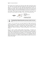
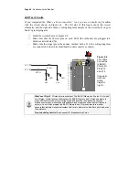
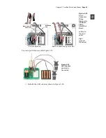
This timing diagram in Figure 2-8 shows the pulse train you are about to send to the LED
with this new program. This time, the high signal lasts for 0.13 seconds, and the low
signal lasts for 2 seconds. This is 100 times slower than the signal that the servo will
need to control its motion.
Vdd (5 V)
Vss (0 V)
0.13 s
0.13 s
2.0 s
Figure 2-8
Timing Diagram
for
PulseP13Led.bs2
√
Enter, save, and run PulseP13Led.bs2.
√
Verify that the LED circuit connected to P13 pulses for about thirteen
hundredths of a second, once every two seconds.
' Robotics with the Boe-Bot – PulseP13Led.bs2
' Send a 0.13 second pulse to the LED circuit connected to P13 every 2 s.
' {$STAMP BS2}
' {$PBASIC 2.5}
DEBUG "Program Running!"
DO
PULSOUT 13, 65000
PAUSE 2000
LOOP
Example Program: PulseBothLeds.bs2
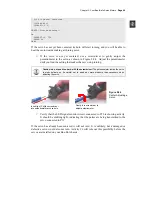
This example program sends a pulse to the LED connected to P13, and then it sends a
pulse to the LED connected to P12 as shown in Figure 2-9. After that, it pauses for two
seconds.

