Chapter 3: Assemble and Test Your Boe-Bot
· Page 105
Your Turn – Testing the Left Wheel
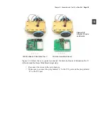
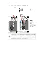
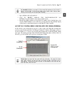
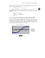
Now, it’s time to run the same test on the left wheel as shown in Figure 3-15. This
involves modifying RightServoTest.bs2 so that the
PULSOUT
commands are sent to the
servo connected to P13 instead of the servo connected to P12.
All you have to do is change the three
PULSOUT
commands so that they read
PULSOUT 13
instead of
PULSOUT 12
.
Figure 3-15
Testing the Left
Wheel
√
Save RightServoTest.bs2 as LeftServoTest.bs2.
√
Change the three
PULSOUT
commands so that they read
PULSOUT 13
instead of
PULSOUT 12
.
√
Save and then run the program.
√
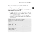
Verify that it makes the left servo turn clockwise for 3 seconds, stops for 1
second, then makes the servo turn counterclockwise for 3 seconds.
√
If the left wheel/servo does not behave as predicted, see the Servo Trouble
Shooting section on page 104.
√
If the left wheel/servo does behave properly, then your Boe-Bot is functioning
properly, and you are ready to move on to the next activity.
ACTIVITY #3: START/RESET INDICATOR CIRCUIT AND PROGRAM
When the voltage supply drops below the level a device needs to function properly, it’s
called brownout. The BASIC Stamp protects itself from brownout by making its
processor and program memory chips go dormant until the power supply voltage returns
to normal levels. A drop below 5.2 V at Vin results in a drop below 4.3 V at the BASIC
Stamp’s internal voltage regulator output. A circuit called a brownout detector on the
BASIC Stamp is always on the lookout for this condition. When brownout occurs, the
brownout detector disables the BASIC Stamp’s processor and program memory.
Counterclockwise 3 seconds
Stop 1 second
Clockwise 3 seconds

