background image

15

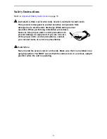
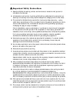
Important Safety Instructions

1. Read and follow all warning notices and instructions marked on the product or 

included in the manual.

2. All installation and service must be performed by qualified service personnel, as 

opening or removing covers may expose dangerous voltage points or other risks.

3. This product is intended to be used with a 3-wire grounding type plug – a plug 

which has a grounding pin. This is a safety feature. Equipment grounding is vital to 
ensure safe operation. Do not defeat the purpose of the grounding type plug by 
modifying the plug or using an adapter.

Prior to installation, use an outlet tester or a voltmeter to check the AC receptacle 
for the presence of earth ground. If the receptacle is not properly grounded, the 
installation must not continue until a qualified electrician has corrected the problem.

If a 3-wire grounding type power source is not available, consult a qualified 
electrician to determine another method of grounding the equipment.

4. Slots and openings in the cabinet are provided for ventilation. To ensure reliable 

operation of the product and to protect it from overheating, these slots and 
openings must not be blocked or covered.

5. Do not allow anything to rest on the power cord and do not locate the product where 

persons will walk on the power cord.

6. Disconnect power before servicing.

7. General purpose cables are provided with this product. A UL Listed/CSA Certified, 

minimum No. 26 AWG, telecommunications cable is provided for connection to the 
network. Use this cable to reduce the risk of fire.

Special cables, which may be required by the regulatory inspection authority for the 
installation site, are the responsibility of the customer.

8. When installed in the final configuration, the product must comply with the 

applicable Safety Standards and regulatory requirements of the country in which it 
is installed. If necessary, consult with the appropriate regulatory agencies and 
inspection authorities to ensure compliance.

9. A rare phenomenon can create a voltage potential between the earth grounds of 

two or more buildings. If products installed in separate buildings are 
interconnected, the voltage potential may cause a hazardous condition. Consult a 
qualified electrical consultant to determine whether or not this phenomenon exists 
and, if necessary, implement corrective action prior to interconnecting the products.

10. Filler panels are provided with the access carrier to cover unused slots. You 

must 

install filler panels on the unused slots to avoid possible injury from electrical shock 
and to maintain compliance with FCC rules.

11. This access carrier must be installed in a complete enclosure such as a cabinet or 

enclosed rack to prevent user access to hazardous circuits.

!

Содержание 9161 Single T1

Страница 1: ...the following Power supply already installed and power cord Power supply fan tray already installed Fan tray for NAMs already installed Baffle for heat deflection including extender brackets for insta...

Страница 2: ...de the 9261 NAM I O to the Dual T1 NAM I O for use in the access carrier Contact your sales representative to order an option Before You Install the Access Carrier Make sure you have A dedicated groun...

Страница 3: ...ration When performing installation procedures however take proper static control precautions to prevent damage to equipment If you are not sure of the proper static control precautions contact your n...

Страница 4: ...Bottom up installation keeps the cabinet from becoming top heavy Install the access carrier into the cabinet rack before installing any cards in the unit Use some type of strain relief to support mult...

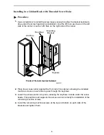
Страница 5: ...ccess carrier against the front rail of the cabinet allowing the installed machine screws on each side to pass through the keyholes 3 Lower the access carrier into place allowing the keyholes to slide...

Страница 6: ...ght side of the carrier Align the hole of the nut with the hole in the rail 2 Place the access carrier against the front rail of the cabinet allowing the installed machine screws to pass through the k...

Страница 7: ...er to the instructions that came with the power supply AC Power Supply for 5 Slot Housing and 9000 Series Access Carrier Installation Instructions Document No 9000 A2 GN17 for installation information...

Страница 8: ...in circulating air and the green LED lights If not check potential reasons in Troubleshooting in the appropriate product manual Installing the Baffle A baffle with self retaining nuts is provided for...

Страница 9: ...3 Using four of the screws provided attach the baffle to the rack immediately below the carrier as shown Baffle 19 Cabinet 23 Cabinet 01 15789 01 Self Retaining Nuts Extender Bracket Self Retaining Nu...

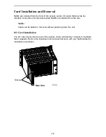
Страница 10: ...ed NAMS are installed from the rear NOTE Cards can be added or removed without powering down the unit I O Card Installation The I O card inserts into the rear of the access carrier and directly connec...

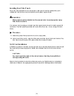
Страница 11: ...1 Select the proper filler panel size to cover empty slots 2 At the rear of the carrier align the filler panel with the upper and lower tracks of the slot then screw the panel into place using the scr...

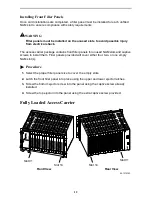
Страница 12: ...unused NAM slots and captive screws to install them Filler panels provided will cover either four two or one empty NAM slot s Procedure 1 Select the proper filler panel size to cover the empty slots...

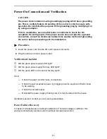
Страница 13: ...h the installation Procedure 1 Insert the power cord into the I O card s power connector 2 Plug the other end into a power outlet Verification Checklist Did the green power supply LED light Did the gr...

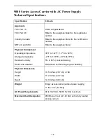
Страница 14: ...ysical Environment Operating temperature Storage temperature Relative humidity Shock and vibration 35 F to 122 F 1 7 C to 50 C 4 F to 158 F 20 C to 70 C 5 to 85 noncondensing Withstands normal shippin...

Страница 15: ...ersons will walk on the power cord 6 Disconnect power before servicing 7 General purpose cables are provided with this product A UL Listed CSA Certified minimum No 26 AWG telecommunications cable is p...

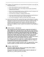
Страница 16: ...imeter in length regardless of the width UNITED STATES EMI NOTICE This equipment has been tested and found to comply with the limits for a Class A digital device pursuant to Part 15 of the FCC rules T...

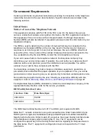
Страница 17: ...ance But if advance notice is not practical you will be notified as soon as possible You will be advised of your right to file a complaint with the FCC Your telephone company may make changes in facil...

Страница 18: ...le Identification SPID number and one local phone number Capability Package R for 2B service which supports up to two circuit switched B channels BRI B1 and BRI B2 with two SPID numbers and two local...

Страница 19: ...the above conditions may not prevent degradation of service in some situations Repairs to certified equipment should be coordinated by a representative designated by the supplier Any repairs or altera...

Страница 20: ...ormation by fax or to speak with a company representative Within the U S A call 1 800 870 2221 Outside the U S A call 1 727 530 2340 Document Feedback We welcome your comments and suggestions about th...

Отзывы: