

2
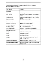
Available Options
The following options can be ordered separately:
72-inch EIA standard cabinet, 19 inches wide
Redundant/replacement power supply
Power supply fan tray
Replacement fan tray for NAMs
Replacement baffle
RJ48H T1 Mass Termination cable for T1 NAMs
FrameSaver 9120 Carrier NAM Upgrade Kit to upgrade a current 1-slot FrameSaver
9120 NAM for use in the access carrier
FrameSaver SLV 9128 1-Slot Housing-to-Access Carrier Upgrade Instructions for
converting a 1-slot FrameSaver SLV 9128 for use in the access carrier
9161 Single T1 NAM Upgrade Kit to upgrade the T1 NAM I/O to the Single T1 NAM
I/O for use in the access carrier
9261 Dual T1 NAM Upgrade Kit to upgrade the 9261 NAM I/O to the Dual T1 NAM
I/O for use in the access carrier
Contact your sales representative to order an option.
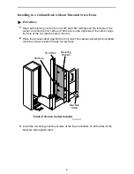
Before You Install the Access Carrier
Make sure you have:
❑
A dedicated, grounded power outlet that is protected by a circuit breaker and
located within 6 feet of the access carrier
❑
A clean, well-lit, and ventilated site that is free from environmental extremes
❑
One-to-two feet of clearance for cable connections
❑
Strain relief material for cable support
❑
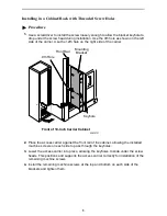
A large Phillips screwdriver to install the access carrier in a cabinet or rack
❑
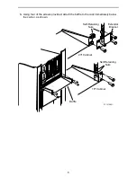
A small or medium Phillips screwdriver to install the I/O card filler panels and front
filler panels
❑
A small, flat-blade screwdriver to install the I/O cards, cable connections, and
redundant power supply (if needed)
❑
Contacted your network provider to coordinate installing the carrier and its
associated cards into the network


