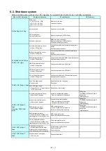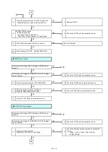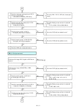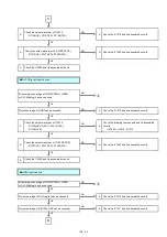
5. 2. 3. Repair
1. Energization check and adjustment, after assembling the lighting block completely.
The service engineer who works on this model and also other people who are in the same room need to wear
the laser safety glasses for avoiding the laser irradiation just in case.
(Usually, if a top case is removed, the interlock switch on A-P.C.Board will detection, and it will stop lighting of a light source. )
2. While the fan is working, do not pull the plug out nor disconnect the breaker.
* When the monitor of power supply lamp turns red and the fan stops, disconnecting can be done.
3. Make sure to turn off the power before repair.
* When replacing the print board, the internal electrical parts can be broken by the static electricity of clothes or
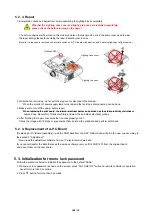
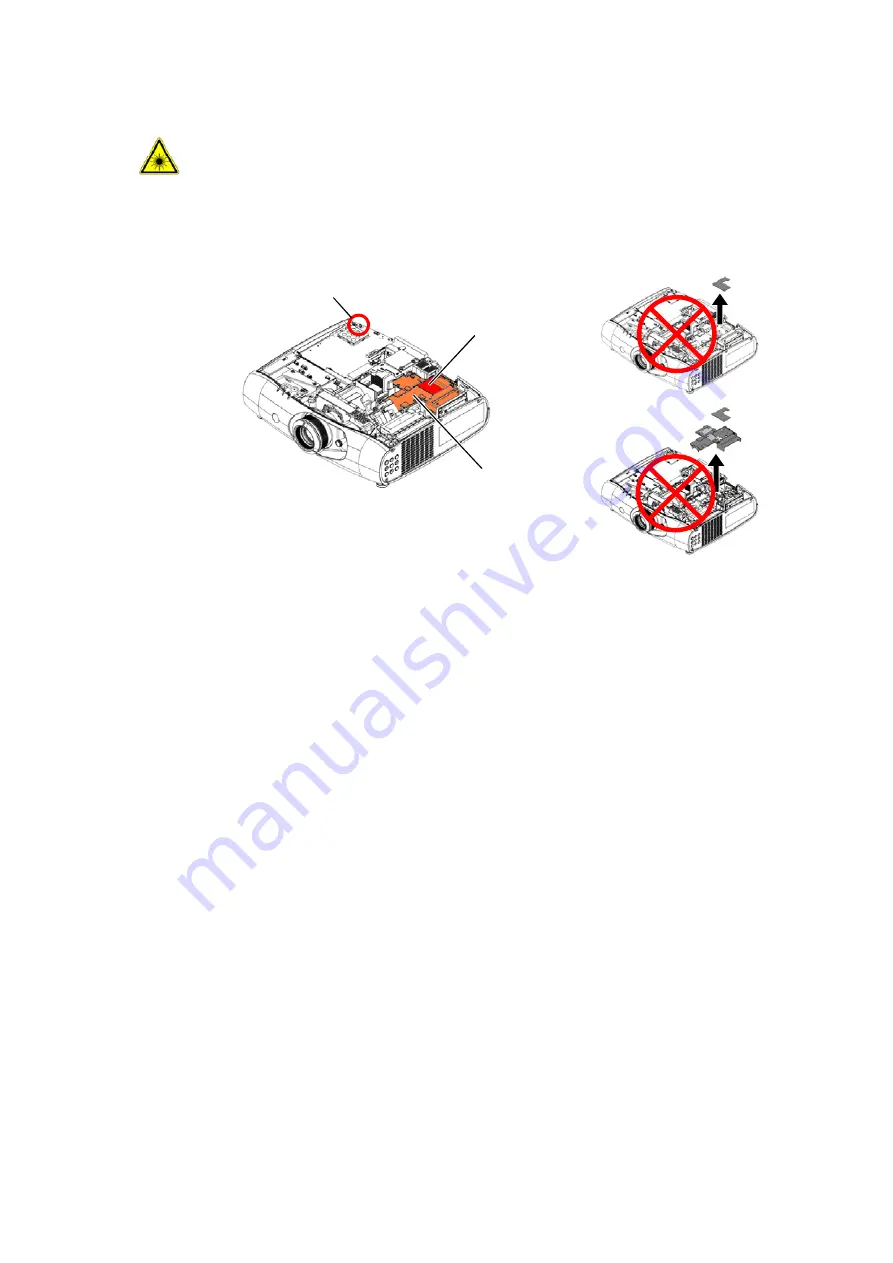
Whether the Lighting case cover and lighting top case are installed completely,
please check the before turning on the power.
Interlock SW
Lighting case cover
Lighting top case
INF - 15
When replacing the print board, the internal electrical parts can be broken by the static electricity of clothes or
human body. Be careful of static electricity and wear the anti-static electricity globes.
4. After finishing the repair, check whether it works properly or not.
Check the image with 10 steps or gray scales that can show the gradation and perform self-check.
5. 2. 4. Replacement of A-P.C.Board
the section 3 "Adjustment".
* Down load the adjustment software from our Projector service web site.
If you cannot transfer the data that uses the service software, remove IC1405/IC1407 from the original board
and mount them on the new board.
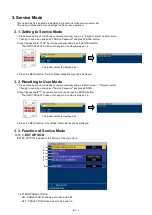
5. 3. Initialization for menu lock password
Follow the procedure below to initialize the password to the default "AAAA".
1. While menu lock password is shown on the screen, press "AUTO SETUP" button on remote controller or operation
panel for more than 2 seconds.
2. Press
button for more than 2 seconds.
If replacing A-P.C.Board (assembly), read the ROM data from the old P.C.Board and write it in the new one according to
INF - 15
Содержание PT-RZ470 Series
Страница 6: ...6 2 Specifications...
Страница 7: ...7...
Страница 9: ...INF 2 1 The name of each part 1 1 Projector body 1 2 Control panel...
Страница 10: ...INF 3 1 3 Connecting terminals 1 4 Remote control...
Страница 11: ...INF 4 2 OSD Menu Navigation...
Страница 12: ...INF 5...
Страница 13: ...INF 6...
Страница 26: ...INF 19 5 Select Log SYSTEM and click Get button 6 Log is displayed...
Страница 84: ......


