165
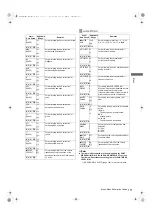
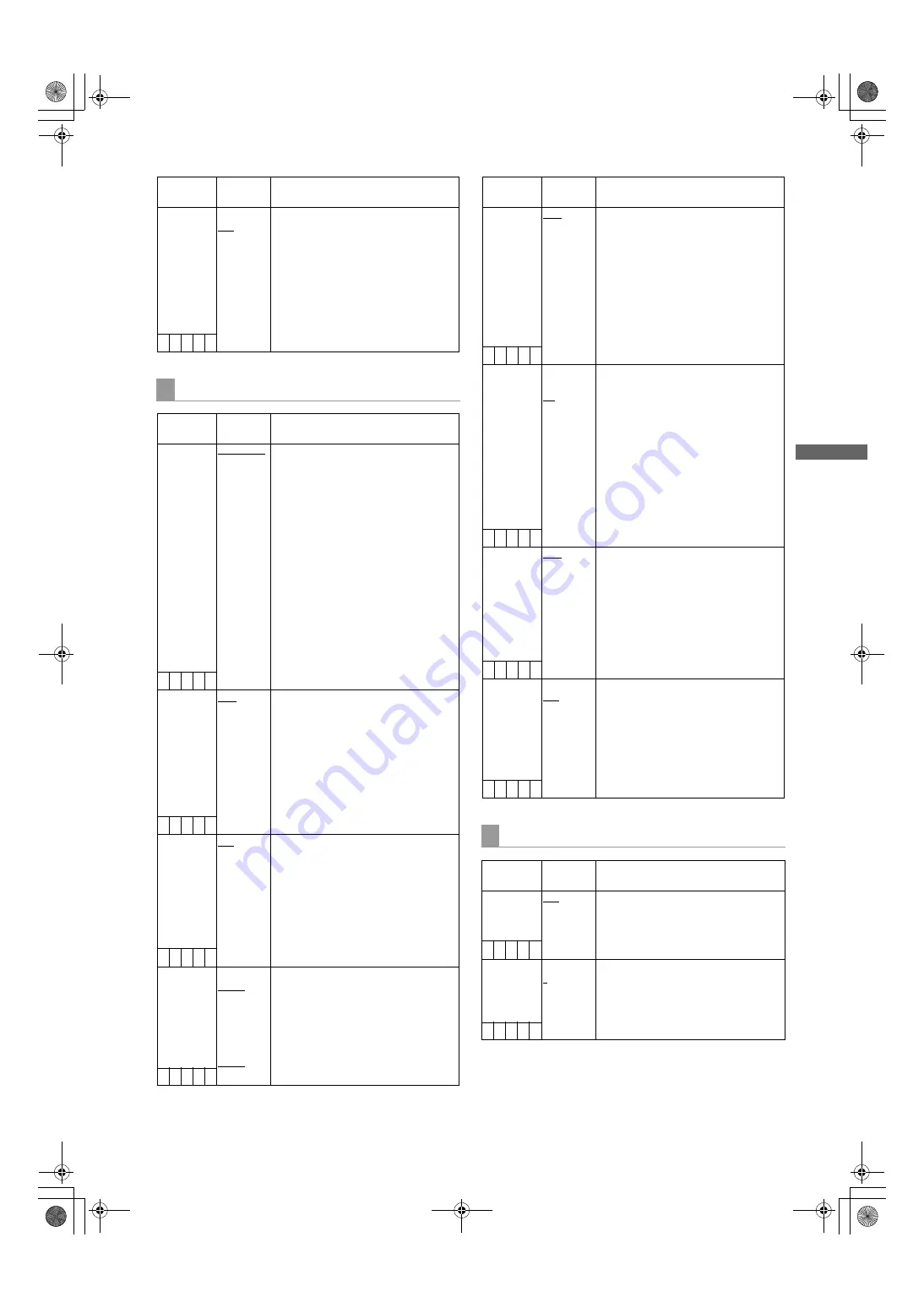
Menu: Menu Description Tables
Men
u
Items/
Data Saved
Adjustable
Range
Remarks
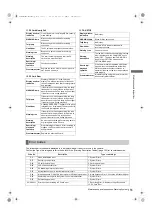
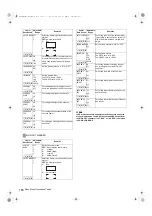
ONE CLIP
REC MODE
ON
OFF
Select the ONE CLIP REC mode.
ON:
Operate in ONE CLIP REC mode.
OFF:
Do not operate in ONE CLIP REC
mode.
Note
This item cannot be changed in the
following cases.
z
When “ON” or “ONE SHOT” is selected
for the INTERVAL REC MODE item.
z
When “ON” is selected for the LOOP
REC MODE item.
– C U F –
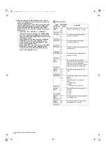
OUTPUT SEL
Items/
Data Saved
Adjustable
Range
Remarks
OUTPUT ITEM MENU ONLY
TC
STATUS
Set the character contents superimposed
onto the output signals for the SDI OUT
connector and MON OUT connector.
MENU ONLY:
Displays only when the menu
characters are superimposed. No
display appears when other characters
are superimposed.
TC:
Display the time code. (Displays the
menu when menu characters are
superimposed.)
Note
The TC display position moves up
and down depending on the camera
ID position.
STATUS:
Display the same characters
superimposed on the viewfinder
signal. (Displays the menu when menu
characters are superimposed.)
– C U F –
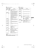
SDI OUT
MODE
MEM
CAM
Select the output signal for the SDI OUT
connector.
MEM:
in playback mode, this is the
playback image.
CAM:
always the camera image.
Note
This item is effective if “CAM” is set for
the REC SIGNAL item in the <SYSTEM
MODE> screen. If “SDI”, then in playback
mode, this will be the playback video
regardless of this setting.
– C U F –
SDI OUT
CHAR
OFF
ON
Select whether to superimpose
characters on the image output from the
SDI OUT connector.
OFF:
Do not superimpose.
ON:
Superimpose.
Note
The content of the superimposed
characters is the same as that
superimposed on video output from the
MON OUT connector
– C U F –
MONITOR
OUT
HD (1080i):
HD SDI
SD SDI
VBS
SD
(480i/576i):
SD SDI
VBS
Select the output signal format for the
MON OUT connector.
HD SDI:
output an HD SDI signal.
SD SDI:
output an SD SDI signal.
VBS:
output a composite signal.
Note
Settings values for HD and SD are stored
separately.
– C U F –
Items/
Data Saved
Adjustable
Range
Remarks
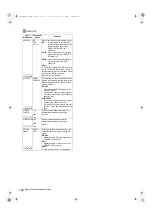
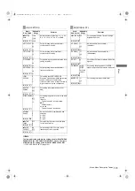
MONITOR
OUT MODE
MEM
CAM
Select the output signal for the MON OUT
connector. This operates separately from
SDI OUT.
MEM:
in playback mode, this is the
playback image.
CAM:
always the camera image.
Note
This item is effective if “CAM” is set for
the REC SIGNAL item in the <SYSTEM
MODE> screen. If “SDI”, then in playback
mode, this will be the playback video
regardless of this setting.
– C U F –
VF/LCD CHAR VF-OFF
LCD-OFF
ON
Select whether to superimpose
characters on the video displayed on the
LCD monitor or in the viewfinder.
VF-OFF:
do not superimpose in the
viewfinder, instead
superimpose on the LCD
monitor.
LCD-OFF:
do not superimpose on the
LCD monitor, instead
superimpose in the
viewfinder.
ON:
superimpose in both the
viewfinder, and on the LCD
monitor.
– C U F –
VF MODE
MEM
CAM
Select the viewfinder image.
MEM: i
n playback mode, this is the
playback image.
CAM:
always the camera image.
Note
This item is effective if “CAM” is set for
the REC SIGNAL item in the <SYSTEM
MODE> screen. If “SDI”, then in playback
mode, this will be the playback video
regardless of this setting.
– C U F –
THUMBNAIL
OUT
ON
OFF
Select whether or not to output clip
thumbnails displayed on the LCD monitor
to the video output and monitor output
signals.
ON:
Enable output.
OFF:
Disable output.
Note
HD SDI signals are being output,
thumbnails are not output.
– C U F –
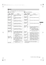
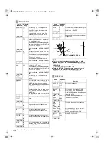
SDI OUT MARKER
Items/
Data Saved
Adjustable
Range
Remarks
MARKER SW OFF
ON
Switches the marker on and off.
OFF:
The characters are not
superimposed.
ON:
The characters are
superimposed.
– C U F R
CENTER
MARK
OFF
1
2
3
4
Switch the center mark.
OFF:
Do not display center mark.
1:
+ (large)
2:
Hollow (large)
3:
+ (small)
4:
Hollow (small)
– C U F R
AJ-HPX3100G(VQT3A79)_E.book 165 ページ 2010年9月17日 金曜日 午後9時21分

