77
Adjustments and Settings for Recording
:
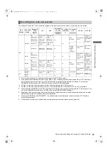
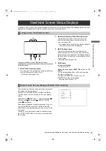
Viewfinder Screen Status Displays
A
d
ju
st
m
ents and
Sett
in
g
s for R
ecord
in
g
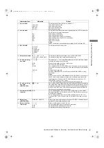
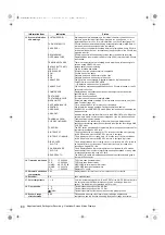
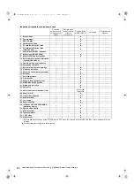
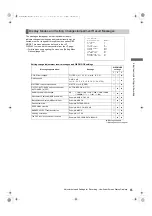
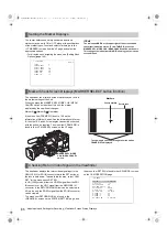
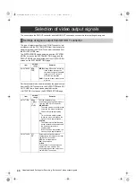
Information Item
Indication
Status
1. System mode
1080-59.9i
1080-50i
480-59.9i
576-50i
This indicates the mode that the unit operates in.
1080-59.94 interlace mode
1080-50 interlace mode
480-59.94 interlace mode
576-50 interlace mode
2. Camera mode
60i
30P
24P
24PA
50i
25P
This indicates the video system when signals output from CCD are recorded
on a P2 card or output as video signals.
1080-59.94i or 480-59.94i
1080-29.97P or 480-29.97P
1080-23.98P or 480-23.98P (2-3 Pull-down)
1080-23.98P or 480-23.98P (2-3-3-2 Pull-down)
1080-50i or 576-50i
1080-25P or 576-25P
Note
In AVC-Intra format, it becomes Native recording for 30P, 24P, and 25P.
3. REC FORMAT
AVC-I 100
AVC-I 50
DVCPRO HD
DVCPRO50
DVCPRO
DV
This indicates the recording mode.
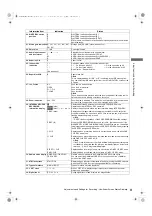
4. Shutter speed/mode
1
1/
¢¢
.
¢
/
1¢¢¢
.
¢
d
1/60 (1/100) - 1/2000, HALF,
¢¢¢
.
¢
d
This indicates that the shutter speed is set to SYNCHRO SCAN.
This indicates that a fixed shutter speed has been set.
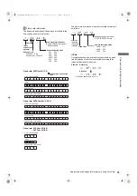
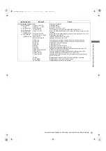
5. P2 card remaining
free space
¢¢¢
min
END
WP
LOOP
INFO P2
¢
/
¢
The indication “
¢¢¢
min” stays illuminated under normal conditions or blinks
when the remaining level is near zero.
When the card space is used up, “END” blinks.
The P2 card is write-protected.
The camera-recorder is in LOOP REC mode. When loop recording cannot be
performed, for example because the P2 card has no free space, the indication
blinks.
P2 card being recognised.
Total free space/capacities of the P2 cards (when MODE CHECK is being
performed).
Note
When the menu item P2 CARD REMAIN is set to “ONE CARD”, the number of
the P2 card slot that contains the target card is indicated, together with the
remaining space. The menu item P2 CARD REMAIN is found in the <VF
INDICATOR> screen on the VF page.
>
[P2 Card Remaining Free Space/capacity Indication] (page 83).
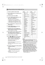
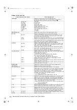
6. P2 card remaining
free space
(MODE CHECK)
¢¢¢
min
The number of the P2 card slot that contains the target card and the remaining
free space (when MODE CHECK is being performed) are indicated. This item
displays the estimated recording time (Refer to [Loop Recording] (page 39))
when in LOOP REC mode. This indication also appears when the target P2
card has been switched with a user button.
7. Camera-recorder REC
indication
REC
This is displayed when the menu item REC TALLY of the is set to “CHAR”.
The menu item REC TALLY is found in the <OPTION MODE> screen on the
SYSTEM SETTING page.
This is displayed when the menu item REC STATUS is set to “ON”. The
menu item REC TALLY is found in the <VF INDICATOR> screen on the VF
page.
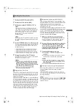
8. Battery type
(MODE CHECK)
DIONIC90 - AC ADPT
Battery type, selected through a menu option. “AC ADPT” indicates when an
external DC power supply has been input.
9. Battery remaining
level/voltage
¢¢
.
¢
V
¢¢¢
%
EMP
MAX
Battery remaining level in tenths of a volt
The remaining battery level is indicated in percentage.
This indicates that the battery level is empty.
This indicates the battery is fully charged.
[1]
AJ-HPX3100G(VQT3A79)_E.book 77 ページ 2010年9月17日 金曜日 午後9時21分

