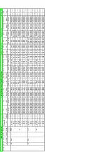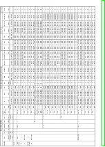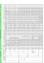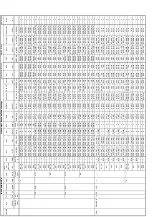
SPECIFICATIONS
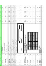
Power supply:
Power consumption:
Dimensions:
Mass:
Operating temperature range:
Operating humidity range:
Pickup:
DVD Signal system:
DVD Region number:
Playable disctype:
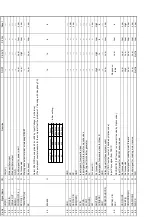
TV tuner system:
RF out system:
Video Recording system:
Video heads:
Video input:
Video output:
DVD RGB video output:
AC220-240 V, 50/60 Hz
22 W +/-1,3W
standby mode: 6W+/-0,4W
430 (W)×270 (D)×89 (H) mm
(excluding protrusions)
3.9kg
+5 to +35°C
35 to 80% RH (no condensation)
Wave length:
662 nm/785 nm
Laser power:
CLASS 1/CLASS 3A
PAL625/50, PAL525/60
NV-VP33
NTSC (playback on PAL TV)
Region No.2
(1) DVD-Video, DVD-RAM, DVD-Audio, DVD-R (R4.7)
(2) CD-Audio (CD-DA), CD-Audio (TEXT)
(3) Video CD (VCD, S-VCD)
(4) CD-R/CD-RW (CD-DA, Video CD formatted discs)
(5) MP3 (audio), WMA (audio), JPG (picture)
Maximum number of tracks and groups recognizable:
Compatible compression rate: between 32 kbps and 320 kbps
4000 tracks and 400 groups
NV-VP23EG/EC/EP
UHF: CH21-CH68
NV-VP28EG/EC
VHF: CHE2-CHE12
NV-VP33EG/EC/EP
UHF: CH21-CH69
NV-VP33EB/EBL
VHF (OIRT): CHR1-CHR12
VHF (CCIR): CHE2-CHE12
UHF: CH21-CH69
CATV (OIRT): 44MHz-470MHz
(CCIR):S1-S5
(CCIR):M1-U10
(CCIR):S21-S41 (8MHz Raster)
NV-VP33EB
UHF: CH21-CH68
UHF: 71 +/-3dBµ, 75 close
NV-VP33EBL
UHF: CH21-CH69
UHF: 71 +/-3dBµ, 75 close
NV-VP23,28,33EG/EC/EP
without RF converter
4 rotary heads
helical scanning system
4 rotary heads
1 pair for recording and
playback (L-R heads)
1 pair for trick play (L’-R’ heads)
EURO AV (AV1 / AV2)
21 pin connector:
1.0 Vp-p, 75 terminated
VIDEO IN (AV3 front input)
cinch connector:
1.0 Vp-p, 75 terminated
EURO AV (AV1 / AV2)
21 pin connector:
1.0 Vp-p, 75 terminated
VHS / DVD cinch connector:
1.0 Vp-p, 75 terminated
DVD (only) cinch connector:
1.0 Vp-p, 75 terminated
S-VIDEO Y
1.0 Vp-p, 75 terminated
S-VIDEO C (PAL)
0.3 Vp-p, 75 terminated
S-VIDEO C (NTSC)
0.286 Vp-p, 75 terminated
R output level:
0.7 Vp-p (75O) +/-10%
G output lebel:
0.7 Vp-p (75O) +/-10%
B output level:
0.7 Vp-p (75 ) +/-10%
Output terminal:
AV (21pin)
Number of terminals:
1 system
Video Recording signal:
PAL
O
O
W
W
W
W
W
W
W
W
W
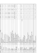
Audio heads:
Audio input:
Audio output:
Audio characteristics:
Dynamic range:
Videotape speed:
Note:
1 stationary head
Mono
2 channels
Hi-Fi Sound-Stereo
EURO AV (AV1 / AV2)
21 pin connector:
-6dBV (500mV), more than 10k
AUDIO IN (AV3 front input)
cinch connector:
-6dBV (500mV), more than 10k
VHS / DVD, DVD only
cinch connector:
-6dBV (500mV), less than 1k
EURO AV (AV1 / AV2)
21 pin connector:
-6dBV (500mV), less than 1k
DVD coaxial output
digital audio output
S/N ratio
Normal: more than 43dB (SP)
Hi-Fi: 65dB,
DVD: 115dB
Frequence responce
Normal: 80Hz - 8kHz,
Hi-Fi: 20Hz - 20kHz
DVD: 4Hz - 22kHz (linear audio)
48kHz sampling
DVD: 4Hz - 44kHz (linear audio)
96kHz sampling
CD Audio: 4Hz - 20kHz
Total harmonic distortion:
CD Audio: 0.0025%
VCR:
more than 90dB
DVD (linear audio):
more than 98dB
CD audio:
more than 96dB
SP:
23.39mm/s
LP:
11.695mm/s
EP:
7.796mm/s
Record / Playback time:
SP: 4hours (240min. tape)
LP:
8hours (240min. tape)
EP:
12hours (240min. tape)
FF / REW time:
60sec. (180min. tape)
Specifications are subject to change without notice.
Mass and dimensions are approximate.
W
W
W
W
MPEG Layer-3 audio decoding technology licensed from Fraunhofer
IIS and Thomson multimedia.
Windows Media, and the Windows logo are
trademarks, or registered trademarks of
Microsoft Corporation in the United States and/
or other countries.
WMA is a compression format developed by
Microsoft Corporation. It achieves the same
sound quality as MP3 with a file size that is
smaller than that of MP3.
■
Built-in decoders
You can play discs with these symbols
.
Содержание NV-VP23-33
Страница 13: ...C Stop unloading just before unloading would be completed D Then the tape becomes slack 13 ...
Страница 18: ...7 3 TOP PANEL 1 Unscrew the Screws 7 4 FRONT PANEL UNIT 1 Unscrew the Screw 2 Remove the Tabs 18 ...
Страница 22: ...7 9 MAIN PCB UNIT 1 Unscrew the Screws 2 Release the Connectors 3 Remove the Main PCB Unit 22 ...
Страница 23: ...7 10 POWER PCB UNIT 1 Unscrew the Screws 2 Release the Connectors 3 Remove the Power PCB Unit 23 ...
Страница 25: ...7 12 2 SERVICE POSITION OF THE POWER SUPPLY PCB 7 12 3 SERVICE POSITION OF THE DECODER PCB AND TERMINAL PCB 25 ...
Страница 39: ...10 3 FRONT HOLDER 1 Remove the Front Holder 10 4 CLAMP PLATE UNIT 39 ...
Страница 56: ...12 ABBREVIATIONS 56 ...
Страница 64: ...20 1 VCR CHASSIS PARTS SECTION 20 2 DVD CHASSIS PARTS SECTION 64 ...
Страница 65: ...20 3 CASING PARTS SECTION 65 ...
Страница 66: ...66 ...
Страница 67: ...20 4 PACKING PARTS SECTION 67 ...
Страница 86: ...LB1218 BEAD CORE J0JHC0000070 1 86 ...
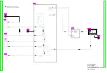
Страница 122: ...5 VID_FROM_YC AV3_V_IN TO SYSCON JK4801 7 6 V_OUT_TO_YC FROM SS SECTION TO IO SECTION PP4801 PS7501 3 3 ...
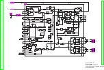
Страница 123: ...NV VP23EG EC EP NV VP28EG EC NV VP33EG EC EB EBL EP VCR LUMINANCE CHROMINANCE 2 2 BLOCK DIAGRAM ...

