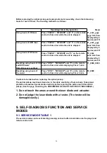
Before replacing the optical pickup unit and spindle motor assembly, check the total using
hours for each of them. The checking method is as follows:
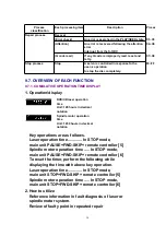
Operating state & Key operation
Display
Using hours of CD laser
Press “PAUSE”, “FWD-SKIP” and “5” on the remote
control in this order while the unit is stopped
T1_xxxx_yyyy
yyyy: total hours
displayed by 4
figures (unit: 10
Using hours of DVD laser
Press “PAUSE”, “FWD-SKIP” and “5” on the remote
control in this order while the unit is stopped
T1_xxxx_yyyy
xxxx: total hours
displayed by 4
figures (unit: 10
Using hours of SP motor
Press “PAUSE”, “FWD-SKIP and “6” on the remote
control in this order while the unit is stopped
T2_xxxx
xxxx: total hours
displayed by 4
figures (unit: 10
Resetting using hours of CD
and DVD lasers
(Simultaneous resetting)
Press “STOP”, “FWD-SKIP” and “5” on the remote
control in this order while displaying Timer 1 data
T1_0000_0000
Resetting using hours of
the motor
Press “STOP”, “FWD-SKIP” and “6” on the remote
control in this order while displaying Timer 2 data
T2_0000
Cautions to be taken when replacing the optical pickup
The optical pickup may break down due to the static electricity of human body. Take proper
protection measures against static electricity before repairing the parts around the optical
pickup. (See the page describing the PREVENTION OF STATIC ELECTRICITYDISCHARGE.)
1. Do not touch the areas around the laser diode and actuator.
2. Do not judge the laser diode with a tester. (The tester will be
damaged easily.)
9. SELF-DIAGNOSIS FUNCTION AND SERVICE
MODES
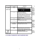
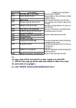
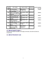
9.1. SERVICE MODE TABLE 1
The service modes can be activated by pressing various button combination on the player and
remote control unit.
28
Содержание NV-VP23-33
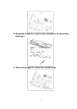
Страница 13: ...C Stop unloading just before unloading would be completed D Then the tape becomes slack 13 ...
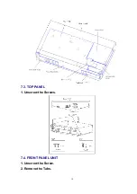
Страница 18: ...7 3 TOP PANEL 1 Unscrew the Screws 7 4 FRONT PANEL UNIT 1 Unscrew the Screw 2 Remove the Tabs 18 ...
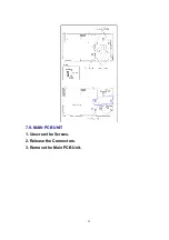
Страница 22: ...7 9 MAIN PCB UNIT 1 Unscrew the Screws 2 Release the Connectors 3 Remove the Main PCB Unit 22 ...
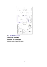
Страница 23: ...7 10 POWER PCB UNIT 1 Unscrew the Screws 2 Release the Connectors 3 Remove the Power PCB Unit 23 ...
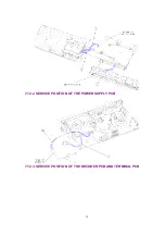
Страница 25: ...7 12 2 SERVICE POSITION OF THE POWER SUPPLY PCB 7 12 3 SERVICE POSITION OF THE DECODER PCB AND TERMINAL PCB 25 ...
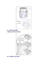
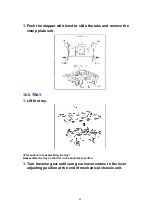
Страница 39: ...10 3 FRONT HOLDER 1 Remove the Front Holder 10 4 CLAMP PLATE UNIT 39 ...
Страница 56: ...12 ABBREVIATIONS 56 ...
Страница 64: ...20 1 VCR CHASSIS PARTS SECTION 20 2 DVD CHASSIS PARTS SECTION 64 ...
Страница 65: ...20 3 CASING PARTS SECTION 65 ...
Страница 66: ...66 ...
Страница 67: ...20 4 PACKING PARTS SECTION 67 ...
Страница 86: ...LB1218 BEAD CORE J0JHC0000070 1 86 ...
Страница 122: ...5 VID_FROM_YC AV3_V_IN TO SYSCON JK4801 7 6 V_OUT_TO_YC FROM SS SECTION TO IO SECTION PP4801 PS7501 3 3 ...
Страница 123: ...NV VP23EG EC EP NV VP28EG EC NV VP33EG EC EB EBL EP VCR LUMINANCE CHROMINANCE 2 2 BLOCK DIAGRAM ...

