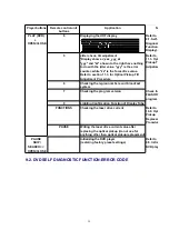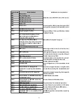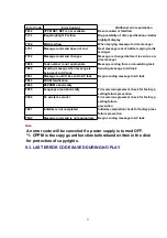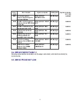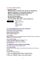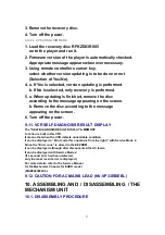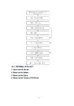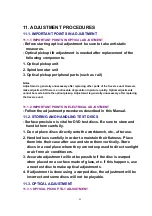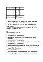
9.7.2. SERVO PROCESS DISPLAY
1. Operation/display
While the player is in STOP mode, perform the specified key
operation to display the servo process number on FL.
When the display does not change from the error
indication, press Open/Close key to show
the servo process number.
Key operation: In STOP mode,
main unit PAUSE+FWD- SKIP+ remote controller [7]
Number to the left ...
... Process number when
halted
Number to the right ...
... Process number in
progress
9.8. SALES DEMONSTRATION LOCK FUNCTION
This function prevents discs from being lost
when the unit is used for sales demonstrations
by disabling the disc eject function.
"LOCK" is displayed on the unit and
ordinary operation is disabled.
9.8.1. SETTING
The sales demonstration lock is set by simultaneously pressing STOP button on the player and
POWER button on the remote control unit.
9.8.2. CANCELLATION
The lock can be cancelled by the same procedure as used
in setting. ("UNLOCK" is displayed on cancellation.
Disconnecting the power cable from power outlet does
not cancel the lock.)
9.9. HANDLING AFTER COMPLETING REPAIRS
Use the following procedure after completing repairs.
9.9.1. PRECAUTIONS
Do not disconnect the power plug from the outlet with the tray still open, then close the tray
manually.
9.9.2. METHOD
Confirm that the power is turned on:
1. Press the "OPEN/CLOSE" button to close the tray.
2. Press the "POWER" button to turn off the power.
35
Содержание NV-VP23-33
Страница 13: ...C Stop unloading just before unloading would be completed D Then the tape becomes slack 13 ...
Страница 18: ...7 3 TOP PANEL 1 Unscrew the Screws 7 4 FRONT PANEL UNIT 1 Unscrew the Screw 2 Remove the Tabs 18 ...
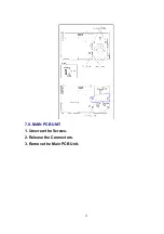
Страница 22: ...7 9 MAIN PCB UNIT 1 Unscrew the Screws 2 Release the Connectors 3 Remove the Main PCB Unit 22 ...
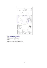
Страница 23: ...7 10 POWER PCB UNIT 1 Unscrew the Screws 2 Release the Connectors 3 Remove the Power PCB Unit 23 ...
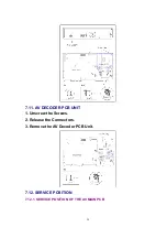
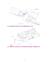
Страница 25: ...7 12 2 SERVICE POSITION OF THE POWER SUPPLY PCB 7 12 3 SERVICE POSITION OF THE DECODER PCB AND TERMINAL PCB 25 ...
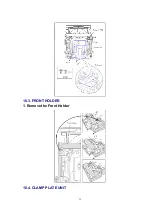
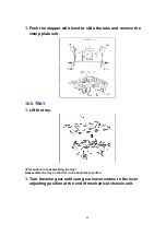
Страница 39: ...10 3 FRONT HOLDER 1 Remove the Front Holder 10 4 CLAMP PLATE UNIT 39 ...
Страница 56: ...12 ABBREVIATIONS 56 ...
Страница 64: ...20 1 VCR CHASSIS PARTS SECTION 20 2 DVD CHASSIS PARTS SECTION 64 ...
Страница 65: ...20 3 CASING PARTS SECTION 65 ...
Страница 66: ...66 ...
Страница 67: ...20 4 PACKING PARTS SECTION 67 ...
Страница 86: ...LB1218 BEAD CORE J0JHC0000070 1 86 ...
Страница 122: ...5 VID_FROM_YC AV3_V_IN TO SYSCON JK4801 7 6 V_OUT_TO_YC FROM SS SECTION TO IO SECTION PP4801 PS7501 3 3 ...
Страница 123: ...NV VP23EG EC EP NV VP28EG EC NV VP33EG EC EB EBL EP VCR LUMINANCE CHROMINANCE 2 2 BLOCK DIAGRAM ...

