3. Disconnect the power plug from the outlet.
9.10. SERVICE PRECAUTIONS
9.10.1. RECOVERY AFTER THE DVD PLAYER IS REPAIRED
When an FROM or an EEPROM on the decoder PCB has replaced, carry out the recovery disc
processing to optimize the drive. Playback the disk to process the recovery automatically.
Note:
This unit requires no initialization process carried out after the traditional DVD players were
repaired.
When the recovery measures are taken, the customer setting will return to the factory setting as
same as the procedure described in item of "Initialization". Write down the contents of the
setting before recovery processing and reset the player.
9.10.2. FIRMWARE VERSION-UP OF THE DVD PLAYER
The firmware of the DVD player may be renewed to improve the quality including
operationability and playability to the substandard discs processing to optimize the drive.
Note:
If the AC power supply is shut down during version-up due to a power failure, the version-up is
improperly carried out. In such a case, replace the FROM and carry out the version-up again.
The product number of the version-up disc will be noticed when it is supplied.
9.10.3. FIRMWARE VERSION-UP AND RECOVERY WITH DISC
- Recovery
- Firmware updating
Simply run the recovery disc. Then both of the above
operations are automatically performed.
Commercially available CD-R can now perform updating
and recovery process, making it easier to update the
version.
Recovery process: Optimization of player after replacement
of FROM and Decoder PCB.
Version updating: Firmware updating for improved
operability and performance.
9.10.4. HOW TO USE RECOVERY DISC
9.10.4.1. PERFORMIG RECOVERY
1. Load the recovery disc RFKZD03R005 on to the player and run it.
2. Recovery is performed automatically. When it is finished,
a message appears on the screen.
36
Содержание NV-VP23-33
Страница 13: ...C Stop unloading just before unloading would be completed D Then the tape becomes slack 13 ...
Страница 18: ...7 3 TOP PANEL 1 Unscrew the Screws 7 4 FRONT PANEL UNIT 1 Unscrew the Screw 2 Remove the Tabs 18 ...
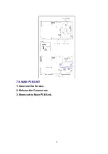
Страница 22: ...7 9 MAIN PCB UNIT 1 Unscrew the Screws 2 Release the Connectors 3 Remove the Main PCB Unit 22 ...
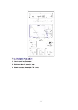
Страница 23: ...7 10 POWER PCB UNIT 1 Unscrew the Screws 2 Release the Connectors 3 Remove the Power PCB Unit 23 ...
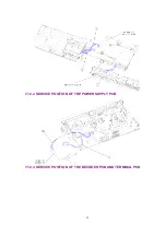
Страница 25: ...7 12 2 SERVICE POSITION OF THE POWER SUPPLY PCB 7 12 3 SERVICE POSITION OF THE DECODER PCB AND TERMINAL PCB 25 ...
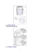
Страница 39: ...10 3 FRONT HOLDER 1 Remove the Front Holder 10 4 CLAMP PLATE UNIT 39 ...
Страница 56: ...12 ABBREVIATIONS 56 ...
Страница 64: ...20 1 VCR CHASSIS PARTS SECTION 20 2 DVD CHASSIS PARTS SECTION 64 ...
Страница 65: ...20 3 CASING PARTS SECTION 65 ...
Страница 66: ...66 ...
Страница 67: ...20 4 PACKING PARTS SECTION 67 ...
Страница 86: ...LB1218 BEAD CORE J0JHC0000070 1 86 ...
Страница 122: ...5 VID_FROM_YC AV3_V_IN TO SYSCON JK4801 7 6 V_OUT_TO_YC FROM SS SECTION TO IO SECTION PP4801 PS7501 3 3 ...
Страница 123: ...NV VP23EG EC EP NV VP28EG EC NV VP33EG EC EB EBL EP VCR LUMINANCE CHROMINANCE 2 2 BLOCK DIAGRAM ...

