installed.
Caution
Be sure no power is applied to the chassis or circuit, and observe
all other safety precautions.
8. Minimize bodily motions when handling unpackaged replacement
ES devices. (Otherwise harmless motion such as the brushing
together of your clothes fabric or the lifting of your foot from a
carpeted floor can generate static electricity (ESD) sufficient to
damage an ES device).
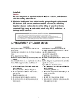
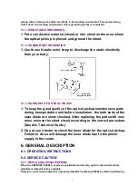
4. PRECAUTION OF LASER DIODE
CAUTION:
ACHTUNG:
This product utilizes a laser diode with the unit
turned “on”,
invisible laser radiation is emitted from the pickup
lens.
Wave length: 662 nm/785 nm
Maximum output radiation power from pickup: 100
W/VDE.
Laser radiation from the pickup lens is on a safety
level, if following precautions are followed:
Dieses Produkt enthält eine Laserdiode.
Im eingeschalteten Zustand wird unsichtbare
Laserstrahlung von der
Lasereinheit ausgestrahlt.
Wellenlänge: 662 nm/785 nm
Maximale Strahlungsleistung der Lasereinheit
/VDE.
Die Strahlung der eingeschalteten Lasereinheit
ungefährlich, wenn
folgende Punkte beachtet werden:
1. Do not disassemble the optical pickup unit,
since radiation
from exposed laser diode is dangerous.
1. Die Lasereinheit nicht zerlegen, da die Strahlung
der freigelegten
Laserdiode gefährlich ist.
2. Do not adjust the variable resistor on the
pickup unit.
It was already adjusted.
2. Den werksseitig justierten Einstellregler der
Lasereinheit nicht
verstellen.
3. Recommend not to look at pickup lens.
3. Nicht in die Fokussierlinse blicken.
4. Do not look at the focus lens using optical
instruments.
4. Auch nicht mit optischen Instrumenten in die
Fokussierlinse blicken.
5
Содержание NV-VP23-33
Страница 13: ...C Stop unloading just before unloading would be completed D Then the tape becomes slack 13 ...
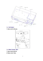
Страница 18: ...7 3 TOP PANEL 1 Unscrew the Screws 7 4 FRONT PANEL UNIT 1 Unscrew the Screw 2 Remove the Tabs 18 ...
Страница 22: ...7 9 MAIN PCB UNIT 1 Unscrew the Screws 2 Release the Connectors 3 Remove the Main PCB Unit 22 ...
Страница 23: ...7 10 POWER PCB UNIT 1 Unscrew the Screws 2 Release the Connectors 3 Remove the Power PCB Unit 23 ...
Страница 25: ...7 12 2 SERVICE POSITION OF THE POWER SUPPLY PCB 7 12 3 SERVICE POSITION OF THE DECODER PCB AND TERMINAL PCB 25 ...
Страница 39: ...10 3 FRONT HOLDER 1 Remove the Front Holder 10 4 CLAMP PLATE UNIT 39 ...
Страница 56: ...12 ABBREVIATIONS 56 ...
Страница 64: ...20 1 VCR CHASSIS PARTS SECTION 20 2 DVD CHASSIS PARTS SECTION 64 ...
Страница 65: ...20 3 CASING PARTS SECTION 65 ...
Страница 66: ...66 ...
Страница 67: ...20 4 PACKING PARTS SECTION 67 ...
Страница 86: ...LB1218 BEAD CORE J0JHC0000070 1 86 ...
Страница 122: ...5 VID_FROM_YC AV3_V_IN TO SYSCON JK4801 7 6 V_OUT_TO_YC FROM SS SECTION TO IO SECTION PP4801 PS7501 3 3 ...
Страница 123: ...NV VP23EG EC EP NV VP28EG EC NV VP33EG EC EB EBL EP VCR LUMINANCE CHROMINANCE 2 2 BLOCK DIAGRAM ...


