42
l
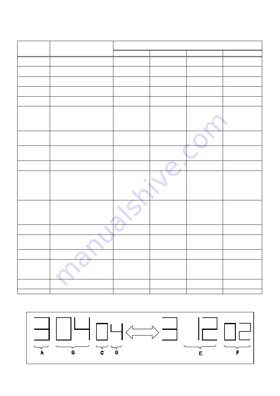
Self-Diagnosis history and Memory of the supplementary data
Supplementary Data
Memory No.
(Error No.)
Reason
Data 1
Data 2
Data 3
Data 4
20/21/22/23
An error during PG Shifter
Automatic Adjustment
VCR mode
No Data
Process No.
No data
80
An exceptional ejection
depends on a Error
VCR mode
Reason of
Ejection
Process No.
No data
18
Detection of T-reel lock during
the constant tape running
VCR mode
Tape position
Process No.
Count of FG
17
Detection of S-reel lock during
the constant tape running
VCR mode
Tape position
Process No.
Count of FG
16
Detection of the Cylinder lock
during the constant rotation
VCR mode
Tape position
Process No.
No data
15
S-reel pulse cannot be
detected when a cassette tape
is inserted.
(Error of the S-reel system or
the Capstan system.)
VCR mode
Counted value of
S-reel pulse
Process No.
Count of FG
14
An exceptional detection of the
DOWN position during the
unloading.
No Data
No Data
Process No.
No data
8
The recording circuit is
operated in except for REC
mode.
VCR mode
No Data
Process No.
No data
7
The recording circuit can not
be operated in REC mode.
VCR mode
No Data
Process No.
No data
6
Mechanism lock during the
Cassette-up.
VCR mode
Stand-by
position
Process No.
LM data
5
S-reel pulse cannot be
detected when a cassette tape
is inserted.
(Error of the S-reel system or
the Capstan system.)
VCR mode
Tape position
Process No.
Count of FG
4
Mechanism lock during
unloading
VCR mode
Stand-by
position
Process No.
LM data
3
Mechanism lock during without
the unloading and the
cassette-up.
VCR mode
Stand-by
position
Process No.
LM data
2
The CAP FG could not be
detected.
VCR mode
No Data
Process No.
Count of FG
1
The cylinder could not be
started.
(Error of the cylinder or the
cylinder drive circuit)
VCR mode
No Data
Process No.
No data
11
Cylinder clogs during the PLAY
mode.
VCR mode
No Data
Process No.
No data
10
Dew detection.
VCR mode
No Data
Process No.
No data
Example:
OFF
ON
STOP KEY
Содержание NV-HV61GN
Страница 20: ...3 1 2 DETAIL OF DISASSEMBLY METHOD 1 REMOVAL OF THE TOP PANEL Remove 2 Screws A Remove 2 Screws B Fig D2 20 ...
Страница 21: ...2 REMOVAL OF THE BACK PANEL Remove 2 Screws C Remove Screw D Unlock 4 Tabs E Fig D3 21 ...
Страница 29: ...10 2 CASING PARTS SECTION 29 ...
Страница 30: ...10 3 PACKING PARTS SECTION 30 ...
Страница 31: ...11 REPLACEMENT PARTS LIST 31 ...
Страница 41: ...C4537 ECJ2VC1H560G CHIP CAPACITOR 41 ...
Страница 44: ...D2002 B0AAED000003 DIODE 44 ...
Страница 47: ...Q1152 2SC3311ASA TRANSISTOR 47 ...
Страница 49: ...R1502 ERJ3GEYJ273V CHIP RESISTOR 49 ...
Страница 54: ...W519 ERJ3GEY0R00V CHIP JUMPER 54 ...
Страница 109: ...4 1 3 PARTS NAME OF R4 MECHANISM Fig M2 ...
Страница 139: ...34 ...


