27
Aim for P2, P3 Posts Adjustment
Fig.M8
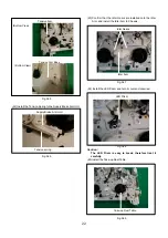
5-2-(2). ADJUSTMENT OF P4 POST
(1) Install A/C Head on the Mechanism Chassis by one
screw.
(2) Playback the Alignment Tape.
(3) Rotate the screw (A) or (B) until the wrinkle appears on
the lower edge of tape at P4 Post.
(4) Rotate the screw (A) or (B) until the wrinkle just
disappears on the lower edge of tape at P4 Post.
(5) Connect the oscilloscope to audio output terminal.
(6) Rotate the screw (C) until audio signal is maximized.
NOTE:
1. The relation between the rotation direction of screws (A)
and (B) and the condition of wrinkle on the lower edge at
P4 Post as shown in Fig.M9.
2. Make sure that there is not the inclined wrinkle between
P4 Post and Pinch Roller.
Fig.M9
P2 Post
P2 Post
P3 Post
P3 Post
P2/P3 Posts
Envelope
Post Name
Adjustment Method
Turn P2 Post counter-clockwise
(Approx. 1/2 revolutions)
Turn P2 Post clockwise
(Approx. 1/4 revolitions)
Turn P3 Post clockwise
Turn P3 Post counter-clockwise
(Approx. 1/2 revolutions)
(Approx. 1/4 revolutions)
Turn P2 Post clockwise
(Less than 1 revolution)
Turn P3 Post counter-clockwise
(Less than 1 revolution)
Содержание NV-HV61GN
Страница 20: ...3 1 2 DETAIL OF DISASSEMBLY METHOD 1 REMOVAL OF THE TOP PANEL Remove 2 Screws A Remove 2 Screws B Fig D2 20 ...
Страница 21: ...2 REMOVAL OF THE BACK PANEL Remove 2 Screws C Remove Screw D Unlock 4 Tabs E Fig D3 21 ...
Страница 29: ...10 2 CASING PARTS SECTION 29 ...
Страница 30: ...10 3 PACKING PARTS SECTION 30 ...
Страница 31: ...11 REPLACEMENT PARTS LIST 31 ...
Страница 41: ...C4537 ECJ2VC1H560G CHIP CAPACITOR 41 ...
Страница 44: ...D2002 B0AAED000003 DIODE 44 ...
Страница 47: ...Q1152 2SC3311ASA TRANSISTOR 47 ...
Страница 49: ...R1502 ERJ3GEYJ273V CHIP RESISTOR 49 ...
Страница 54: ...W519 ERJ3GEY0R00V CHIP JUMPER 54 ...
Страница 109: ...4 1 3 PARTS NAME OF R4 MECHANISM Fig M2 ...
Страница 139: ...34 ...


