54
11-2.CYLINDER DRIVE AND LOADING MOTOR DRIVE CIRCUIT
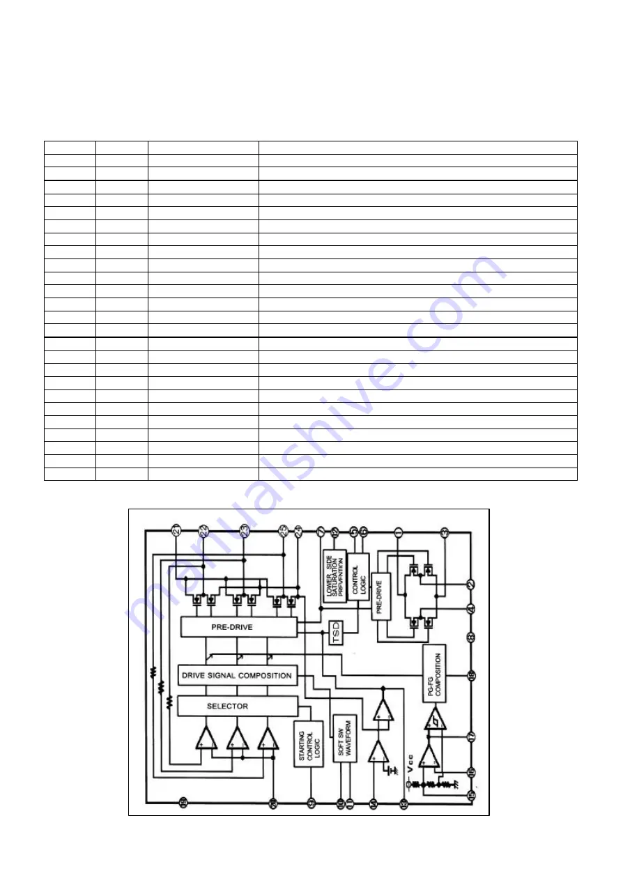
The Cylinder and Loading Motor IC is combined one piece of IC named IC2501.
The simplified block diagram and I/O chart for IC2501 are shown below.
IC2501 (BD6656FP-E2)
I/O CHART
PIN NO.
I/O
TERMINAL NAME
DESCRIPTION
1
IN
VM2
Power of the loading section.
2
OUT
OUT 1
Motor output of the loading motor.
3
---
L GND
GND of motor output of the loading section.
4
OUT
OUT 2
Motor output of the loading motor.
5
IN
F IN
Control input of the loading section.
6
IN
R IN
Control input of the unloading section.
7
IN
VG
Power for DMOS VG.
8
---
GND
GND for the signal section.
9
IN
CST
Capacitor connection terminal for oscillation of cylinder starting.
10
IN
CT 1
Capacitor connection terminal for slope of the cylinder.
11
IN
CT 2
Capacitor connection terminal for slope of the cylinder.
12
IN
PC 1
Capacitor connection terminal for phase compensation of the cylinder.
13
IN
CNF
Capacitor connection terminal for phase compensation of the cylinder.
14
IN
EC
Torque order input terminal for the cylinder.
15
IN
PG +
PG + input terminal for the cylinder.
16
IN
PG -
PG - input terminal for the cylinder.
17
OUT
PG OUT
PG 3 state output terminal.
18
OUT
PFG OUT
PG/FG 3 state output terminal.
19
IN
VCC
Power for the signal section.
20
IN
COM
Center of the cylinder motor coils.
21
IN
VM 1
Power terminal for the cylinder motor.
22
OUT
U
Output terminal for the cylinder motor.
23
OUT
V
Output terminal for the cylinder motor.
24
IN
RNF
GNG for the cylinder motor.
25
OUT
W
Output terminal for the cylinder motor.
IC2501 (BD6656FP-E2) INTERNAL BLOCK DIAGRAM
Содержание NV-HV61GN
Страница 20: ...3 1 2 DETAIL OF DISASSEMBLY METHOD 1 REMOVAL OF THE TOP PANEL Remove 2 Screws A Remove 2 Screws B Fig D2 20 ...
Страница 21: ...2 REMOVAL OF THE BACK PANEL Remove 2 Screws C Remove Screw D Unlock 4 Tabs E Fig D3 21 ...
Страница 29: ...10 2 CASING PARTS SECTION 29 ...
Страница 30: ...10 3 PACKING PARTS SECTION 30 ...
Страница 31: ...11 REPLACEMENT PARTS LIST 31 ...
Страница 41: ...C4537 ECJ2VC1H560G CHIP CAPACITOR 41 ...
Страница 44: ...D2002 B0AAED000003 DIODE 44 ...
Страница 47: ...Q1152 2SC3311ASA TRANSISTOR 47 ...
Страница 49: ...R1502 ERJ3GEYJ273V CHIP RESISTOR 49 ...
Страница 54: ...W519 ERJ3GEY0R00V CHIP JUMPER 54 ...
Страница 109: ...4 1 3 PARTS NAME OF R4 MECHANISM Fig M2 ...
Страница 139: ...34 ...


