No. SX-DSV02829 -
21-
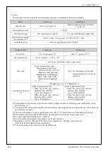
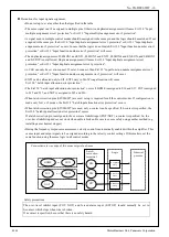
(2) [Reallocation of output signal].
To change the allocation of output signal, change the following parameters.
Class
No.
At-
trib-
ute *1)
Title
Range
Unit
Function
4
10
C
SO1 output
selection
0–
00FFFFFFh
—
Assign functions to SO1 outputs.
These parameters are presented in hexadecimals.
Hexadecimal presentation is followed by a specific control mode
designation.
0 0 – – – – * * h: position control
0 0 – – * * – – h: velocity control
0 0 * * – – – – h: Torque control
Replace * * with the function number.
For the function number see the table below.
4
11
C
SO2 output
selection
0–
00FFFFFFh
—
Assign functions to SO2 outputs.
Setup procedure is the same as described for Pr 4.10.
4
12
C
SO3 output
selection
0–
00FFFFFFh
—
Assign functions to SO3 outputs.
Setup procedure is the same as described for Pr 4.10.
*1) For parameter attribute, refer to Section 9-1.
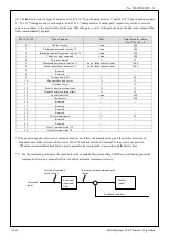
Function number table
Title of signal
Symbol
Setup value
External output
Invalid
—
00h
Alarm output
ALM
01h
Servo-Ready output
S-RDY
02h
External brake release signal
BRK-OFF
03h
Positioning complete output
INP
04h
At-velocity output
AT-SPEED
05h
Torque in-limit signal output
TLC
06h
Zero-speed detection output signal
ZSP
07h
Speed matching output
V-COIN
08h
Warning output1
WARN1
09h
Warning output2
WARN2
0Ah
Positional command ON/OFF output
P-CMD
0Bh
Positioning complete 2
INP2
0Ch
Speed in-limit output
V-LIMIT
0Dh
Alarm attribute output
ALM-ATB
0Eh
Velocity command ON/OFF output
V-CMD
0Fh
General purpose output 1
EX-OUT1
10h
set brake output *1)
set brake
11h
Estimated pole position output
CS-CMP
12h
*1) “set brake output“ is reversal from logic of 60FEh(digital output).
When 60FEh is “1”, the output signal is “OFF” (brake is activate).
R1.00
Motor Business Unit, Panasonic Corporation

