


196
Cha
p
ter 7
Calculation
, Anal
ysis
, a
nd Out
p
ut o
f Ins
p
ection Result
s
7.5.5 Changing
the
Number of Rows and Columns
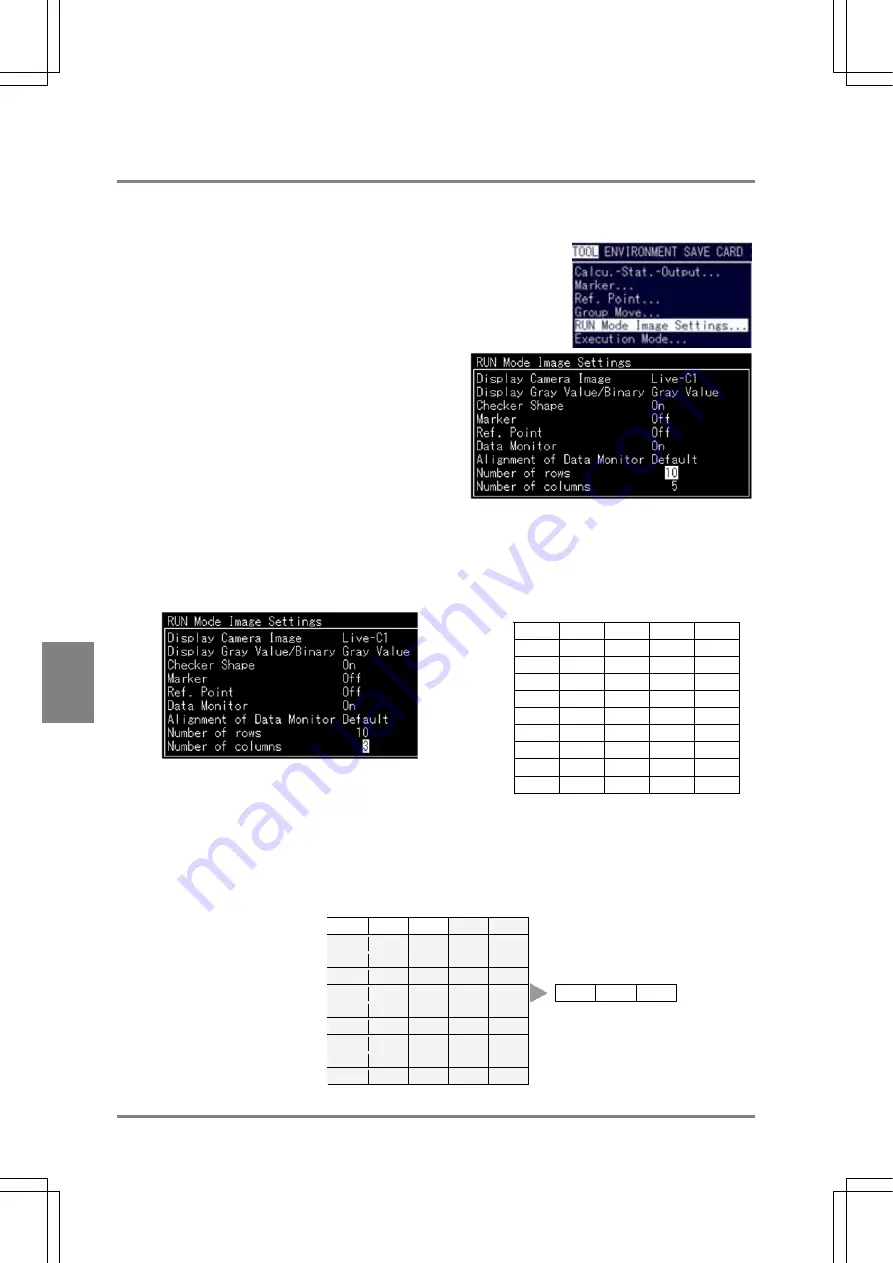
With this feature, you can specify the number of rows and columns in the Data Monitor table to be displayed. The
number of data to be displayed in the Data Monitor table differs depending on the specified number of rows and
columns.
1. Select “TOOL” >”RUN Mode Image Settings”
from the menu bar.
The subwindow is displayed.
2. Highlight “Number of Rows” and specify the
number of rows within the range between 1 and
10.
The specified number of rows is added below the left
upper cell. For example if you choose “1”, only the
top (first) row is displayed.
3. Select “Number of Columns” and specify the number of columns within the range between 1 and 5.
The specified number of columns is added. If you choose “3”, only three columns from the left are
displayed.
The specified number of columns is
displayed.
→
The desired
number of
rows is
displayed.
↓
Example Data Monitor table:
If the number of rows = 1 and the number of columns = 3,
Three columns are
displayed.
↓
The other
columns are
not displayed
↓
Actual
display
↓
One row is displayed.
Æ
TYPE
CA01
CA02
CA03
QS00
TYPE
CA01
The other rows are not
displayed.
Æ
Содержание Micro-Imagechecker PV310
Страница 1: ......
Страница 9: ...1 Names and Functions of Parts Chapter 1 Chapter 1 Names and Functions of Parts ...
Страница 22: ......
Страница 23: ...15 Installation and Wiring Chapter 2 Chapter 2 Installation and Wiring ...
Страница 35: ...27 Input and Output Interface Ports Chapter 3 Chapter 3 Input and Output Interface Ports ...
Страница 47: ...39 Input and Output Interface Ports Chapter 3 Example of Wiring Connections with a PC IBM PC AT ANM81103 ...
Страница 63: ...55 Chapter 5 Procedure for Setting Inspection Conditions Chapter 5 Procedure for Setting Inspection Conditions ...
Страница 76: ......
Страница 107: ...99 Setting Checkers Chapter 6 6 7 Gray Edge 6 7 1 Menu Options ...
Страница 114: ...106 Setting Checkers Chapter 6 6 8 Feature Extraction 6 8 1 Menu Options ...
Страница 121: ...113 Setting Checkers Chapter 6 6 9 Smart Matching 6 9 1 Menu Options ...
Страница 137: ...129 Setting Checkers Chapter 6 6 11 Flaw Detection 6 11 1 Menu Options ...
Страница 207: ...199 TOOL Chapter 8 Chapter 8 TOOL ...
Страница 224: ......
Страница 225: ...217 Environment Settings Chapter 9 Chapter 9 Environment Settings ...
Страница 249: ...241 Chapter 10 Parallel Communication Chapter 10 Parallel Communication ...
Страница 265: ...257 Chapter 11 RS 232C Communication Chapter 11 RS 232C Communication ...
Страница 298: ......
Страница 299: ...291 Chapter 12 Ethernet Communication Chapter 12 Ethernet Communication ...
Страница 303: ...295 Chapter 13 Using a Compact Flash Memory Card Chapter 13 Using a Compact Flash Memory Card ...
Страница 323: ...315 Chapter 15 Troubleshooting Chapter 15 Troubleshooting ...
Страница 328: ......
Страница 329: ...321 Chapter 16 Camera Switching Unit Chapter 16 Camera Switching Unit ...
Страница 333: ...325 Chapter 17 General Specifications Chapter 17 General Specifications ...
Страница 340: ......
Страница 341: ...333 Chapter 18 Product Numbers Chapter 18 Product Numbers ...
Страница 347: ...339 Chapter 19 Dimensions Chapter 19 Dimensions ...
Страница 349: ...341 Chapter 19 Dimensions Double Speed Random Camera C Mount ANM831 Unit mm ...
Страница 352: ...344 Dimensions Chapter 19 ANM88281 ANM88081 ANM8804 ANM88161 ANM88251 Unit mm ...
Страница 356: ......
Страница 357: ...349 Chapter 20 Appendix Chapter 20 Appendix ...
Страница 358: ...350 Appendix Chapter 20 20 1 Pin Assignment of Camera Double Speed Random Camera ANM831 ...
Страница 359: ...351 Chapter 20 Appendix Standard Camera ANM832 ANM83203 ...
Страница 363: ...355 Record of Changes Manual No Date Revision detail ARCT1F456E March 2009 First Edition ...


