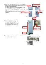
⑬
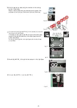
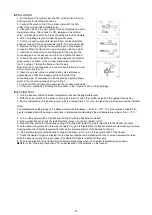
Bend the valve tip downward at 90 degree.
After inserting the gas pipe, fill the gap with silicon.
⑭
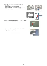
⑮
Insert the valve pipe from the back and secure it with the
mounting plate.
When the cover is attached, the tip of the valve pipe does not
interfere with the cover.
Fix the solenoid valve cover to the position shown in the figure with 2
truss tapping screws M4x12.
Cover the backup cover so that the various harnesses are not
caught in, and fix the four places with screws.
insert hole for
securing clearance
chamber
cover
Foaming
View of side
insert hole for gas tube
connect to harness
Foaming
Fig.13-1
Fig.13-2
Fig.13-3
Fig.14-1
Fig.15-1
-69-
Содержание MDF-DU502VH
Страница 8: ...Dimension MDF DU502VH 5 ...
Страница 9: ...MDF DU702VH 6 ...
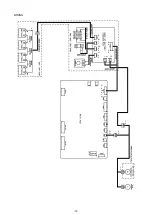
Страница 17: ...Wiring Diagram 14 ...
Страница 18: ...main Circuit Diagram 15 ...
Страница 19: ...power 16 ...
Страница 20: ...USB 17 ...
Страница 73: ...WIRING YG Y Y GR B G W W W Y G R BL Y W R R BL R OR B BL R OR B Y W Y G Y G R BL 70 ...

