background image

Wiring Diagram

-14-

Содержание MDF-DU502VH

Страница 1: ...Service Manual Ultra Low Temperature Freezer MDF DU502VH MDF DU702VH Panasonic Healthcare Co Ltd Biomedical Div SM0000002 03 ...

Страница 2: ...ive model This service manual is effective for following models Model Voltage Frequency MDF DU502VH PA 220V 60Hz MDF DU502VH PE 220V 230V 240V 50Hz MDF DU702VH PA 220V 60Hz MDF DU702VH PE 220V 230V 240V 50Hz ...

Страница 3: ...i a g r a m 1 4 C i r c u i t d i a g r a m 1 5 O p e r a t i o n 1 8 C o n t r o l s p e c i f i c a t i o n s 2 5 I n v e t e r s i g n a l 3 3 P a r t s l a y o u t 3 4 R e p a i r i n g u n i t G a s c h a r g e 3 6 T e s t d a t a 5 2 M D F D U 5 0 2 V H M D F D U 7 0 2 V H P u l l d o w n P u l l u p t e m p e r a t u r e P u l l d o w n t e m p e r a t u r e P u l l d o w n p r e s s u r e ...

Страница 4: ...air intake port Enhancement of safety functions New control panel with LCD touch panel Caution Parts replacement and option unit installation must be done by trained service engineer Service engineer must refer to the section Electric parts and Cooling unit parts about the parts for those operations 1 ...

Страница 5: ...ascade Low Tube on sheet Condenser High Fin and tube Low Cascade Refrigerant HighTemp side LowTemp side HighTemp side LowTemp side R290135g 5g R170 70 g 3 g n pentane 10 g 16cc 0 3 g 12 5 wt R290135g 5g R170 85 g 3 g n pentane 12 g 19cc 0 3 g 12 5 wt Refrigerant oil Ze NIUSL22SA Battery For power failure alarm Lead storage battery DC6 V 7200 mAh Auto recharge Weight 246 kg 278 kg Accessories 1 key...

Страница 6: ...ter alarm indicator is lit when the excessive dust is accumulated on the condenser filter When this indicator is lit clean the condenser filter Remote alarm Remote alarm terminal 3P contact capacity DC 30 V 2 A Max Remote alarm activates when temp alarm or power failure occur Parts replace ment notificati on Battery age Two type of battery accumulation time display in service mode At replacement t...

Страница 7: ... consumption 430 W Max 820 W PA 420 W Max 840 W PE 545 W MAX 930W 945 W 960 W PE 550 W MAX 930 W PA Rated heat radiation 1548 kJ h Max 2952 kJ h 1512 kJ h Max 3024 kJ h 1962 kJ h Max 3348 kJ h 3402 kJ h 3456 kJ h PE 1980 kJ h Max 3348 kJ h PA Noise level 52 dB A background noise 20 dB Maximum pressure 2200 kPa 2200 kPa Maximum cooling performance The chamber temperature can be reached at 86 at amb...

Страница 8: ...Dimension MDF DU502VH 5 ...

Страница 9: ...MDF DU702VH 6 ...

Страница 10: ...40 V 50 60 Hz Condenser Type Finless tube Finless tube Condenser 12 columns x 2 lines 5pitch Fin 50spc Coil pipe Φ6 35 mm Pre condenser W250 mm within 1column x6lines pre con Frame pipe Φ6 35mm Evaporator Type Accumulator Cascade condenser Shell Tube Φ80 mm Φ38 mm Tube on sheet Φ7 94mm Sharing with interior Accumulator Φ38mm Capillary tube Resistance 78 PSI 4 0 kg cm2 Length 3000 mm 2000 mm Outer ...

Страница 11: ...220 240 V 50 60 Hz Condenser Type Finless tube Finless tube Condenser 12 columns x 2 lines 5pitch Fin 50spc Coil pipe Φ6 35mm Pre condenser W250 mm within 1column x6lines pre con Frame pipe Φ6 35mm Evaporator Type Cascade condenser Shell Tube Φ80mm Tube on sheet Φ7 94mm Sharing with interior Accumulator Φ38mm Capillary tube Resistance 78PSI 4 0 kg cm2 Length 3000mm 2000mm Outer diameter Φ2 4mm Φ1 ...

Страница 12: ...drator L Evaporator High temperature header Pre Condenser Cascade Dehydrator Frame Pipe Compressor L Suction heat exchanger Capillary Tube L Capillary Tube H Low temp Condenser Compressor H Binary refrigerating cuircuit cascade system MDF DU502VH DU702VH 9 ...

Страница 13: ...emp sensor CN103 1 3 FM cond CN12 1 3 Battery SW CN14 1 6 Backup Battery PCB CN5 1 7 USB PCB 8 9 Door SW CN11 1 2 Main Battery SW CN3 Remote alarm terminal 1 COM 2 N O 3 N C CN7 1 2 Cascade sensor 3 4 Filter sensor CN17 1 2 AIP heater CN15 1 3 Inverter L 4 6 Inverter H CN4 1 2 Jumper for emulator CN1 Emulator 10 ...

Страница 14: ...perature CN7 1 2 Cascade sensor 3 4 Filter sensor To detect temperature of cascade To detect temperature of filter CN8 1 2 AT sensor To detect ambient temperature CN9 1 4 Unused CN11 1 2 Main battery switch To supply power during power failure CN12 1 3 Battery switch To supply power during power failure CN14 1 6 Back up battery charging PCB To control battery charging CN15 1 3 Inverter L 3 6 Inver...

Страница 15: ...or Type Pt THC 663 Pt THC 663 Rating 1000Ω 1000Ω Cascade sensor Type 502AT 11 502AT 11 Rating 5 kΩ 25 5 kΩ 25 Filter sensor Type 502AT 11 502AT 11 Rating 5 kΩ 25 5 kΩ 25 Door Switch Type SDKNA20700 SDKNA20700 Rating 5 V 5 mA 5 V 5 mA Battery Type LC P067R2J LC P067R2J Rating 6 V 7 2 AH 6 V 7 2 AH Battery Switch Type SLE6A2 5 SLE6A2 5 Rating 4 A 250 VAC 4 A 250 VAC Power Switch Type JW L21RRK P4G J...

Страница 16: ...6 013 17 28 16 2 12 22 25 5 000 16 26 88 3 11 73 30 4 179 15 25 66 4 11 25 35 3 508 14 24 52 5 10 80 40 2 961 13 23 43 6 10 37 45 2 509 12 22 39 7 9 960 50 2 137 11 21 41 8 9 569 55 1 826 10 20 48 9 9 196 60 1 567 9 19 59 10 8 840 8 18 74 11 8 496 The following shows the temperature in thermal control sensor PT1000Ω and its resistance value Temp Resistance Value Ω Temp Resistance Value Ω Temp Resi...

Страница 17: ...Wiring Diagram 14 ...

Страница 18: ...main Circuit Diagram 15 ...

Страница 19: ...power 16 ...

Страница 20: ...USB 17 ...

Страница 21: ...rsion UP Update the firmware of main board and touch panel Temp Calibration Chamber adjustment method System Configuration 1 Setting Capi Heater and its timer compressors Fan A B Status Monitoring of chamber temp ambient temp comp evaporator and fan System Configuration 2 Turning On Off of AIP heater and Backup Setting overload alarm delay Reset Data Initialization of data and flash memory Setting...

Страница 22: ...isplayed If an error other than Verify check occurs during version upgrade Firmware rewrite failure is displayed If a Verify error occurs in the Verify check Verify check NG is displayed Service code 384 When some version up files are plurality the first found file is used for version up During appearance wheel all operations are not able to receive OK button in Result screen is disable and all op...

Страница 23: ...lay touch Temp Calibration key Move to input value display Input measured value by thermometer Touch mark area Touch TOP key so return to Menu display Input value area return to zero NOTE Ambient Temp sensor and condenser A B sensor can calibrate in the same procedure Keep touching MENU KEY 5 sec Move to Service Code input display so input 335232 43 3 43 3 43 3 20 ...

Страница 24: ...n once in 18 hours 1 Force on now 2 Force off now default Comp Control Compressor control setting 0 Off 1 On 2 Auto default 3 Manual FAN control setting 0 Off 1 On 2 Auto default Refer to Control Specification for Capi Heater Start Comp Control FAN Control Move to Menu display touch Service 2 key Move to Service display touch System Configuration 1 key 21 ...

Страница 25: ...iguration 2 AIP Heater ON OFF AIP Heater set Backup Function Backup function set Refer to backup cooling kit Overload Alarm Delay Set Overload Alarm Delay 1 6 hour 2 2 day 3 5 day Default Note Use for validation Move to Status display Move to next page 22 ...

Страница 26: ...lure is displayed If communication is successful output error log data 2 048 bytes to USB memory in binary format file name ErrorLog bin During communication and output wheel appear in the screen It outputs log information of all seven periods including service service mode 2 in the CSV format to the USB memory Actual Temp Filter Temp Cascade Temp Ambient Temp Door Opening Output alarm information...

Страница 27: ...ions warning message is displayed and the process break When the output complete Export complete is displayed in Result box If the previous saved setting data exit in USB memory the data is overwritten Data Import Confirm the existence of file in predefined folder of the USB memory If file is not existence or CRC does not match File not found is displayed in Notice screen and the process end If fi...

Страница 28: ...ODE During normal operation ON Basically it is the same as NORMAL model and both comp s are always ON without temp control The rotational speed is maintained constant speed operation During security operation chamber temp unknown OFF Both comp s are always OFF Demo mode Power failure Security operation comp protection temp alarm 5 Condition and Priority of comp operation mode The condition and the...

Страница 29: ... side start threshold 1 condition short 60 sec Cascade temp is below threshold 20 C and within 2 hours from the L side stop long 480 sec Other than those above After security operation After the L side stop the threshold 4 min elapsed After the H side start 1min elapsed The cascade temp is less than 34 C or 15 min elapse from the above H side stop condition OR the chamber tempreture is lower than ...

Страница 30: ... mode change the L side rotational speed from 3000 to 3150 Set temp is 86 C or less Chamber temp is 83 C or less return to 3000 rpm at 82 C over If the following conditions change the rotation speed during PID control from 3000 to 3150 Set temp is 83 C or less 3 Fan control 1 Control The fan is operated in the following mode against the compressor operation table FAN operation mode Name Operation ...

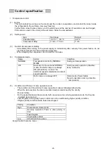
Страница 31: ...5 AIP heater control This heater is always turned ON but for energy saving or protection of abnormal heating is turned OFF under the following conditions Heater OFF condition When the chamber temp is more than 39 turn off when it is less than 40 turn ON Opening the door On power failure or demo mode 6 Buzzer control Refer to the following to the types and specifications or buzzer sound and the bee...

Страница 32: ...de inverter communication failure Warning alarm Communication failure more than 20 consecutive occurrences more than 20 consecutive occurrences after reset timeout more than 10 consecutive times circuit board short W07 L side inverter communication failure Warning alarm Communication failure more than 20 consecutive occurrences more than 20 consecutive occurrences after reset timeout more than 10 ...

Страница 33: ...ound again Set range of ring back restrict input by touch panel side Ring back function OFF 1min 99min default 30min 4 Remote alarm This is linkage with alarm buzzer output And restrict the output from remote alarm port if the alarm buzzer output the remote alarm output too However when the buzzer alarm is no linkage even if the alarm is mute status the remote alarm keep output Remote alarm set Bu...

Страница 34: ... fix Offset value 1 0 1 0 fix Ambient temp correct 1 0 1 0 fix ON OFF adjustment value existance existance fix FAN control Control mode AUTO AUTO Control modes ON point 27 27 20 40 OFF point 26 26 fix Capi heater control Control ON OFF ON ON ON OFF Control mode OFF OFF ON OFF AUTO Maximum cooling time 60 min 60 min fix Action interval Every 18 hour Every 18 hour fix AIP heater control Control ON O...

Страница 35: ... 5 or less fix Sensors open alarm 4950mV 4950mV fix Sensors short alarm 25mV 25mV fix Battery SW judgment 100mV 100mV fix Port heater voltage judgement 0 2V 0 2V fix Range over of ambient temp 0 35 0 35 fix Overload running notice 5 day 5 day 6hour 2day 5day 1 Battery change notice 1022 day 1022 day fix Touch panel communication error 130 sec 130 sec fix Backup battery changing failure 0 3V 6 hour...

Страница 36: ...s of the compressor and the inverter signal verification of the inverter side is necessary 2 The error signal on the inverter side is as follows Failure Mode LED operation Normal operation 1 blink each 15 s Thermostat failure 2 blinks each 5 s Inverter failure 3 blinks each 5 s Compressor failure 4 blinks each 5 s 33 ...

Страница 37: ... Left side Door latch support Inner door latch support Inner door latch Handle Air intake port Chamber Lower Right side PT sensor Battery switch Power switch Remote alarm terminal Lower front Air intake vent Grill Space for Temperature recorder Option auto air intake port Rear side Parts layout 34 ...

Страница 38: ... Lower right side Electric Box Main PCB メイン基板 Lower front Condenser Rear bottom Cooling UNIT Compressor L Compressor H Inverter L Inverter H 35 ...

Страница 39: ...of vacuum pump Powerful vacuum pump Piercing tool 2 to 4 Service valve Service port check valve See work contents in 2 1 Valve driver Scale electronic weighing scale Coupler Pinch pliers 2 Nitrogen cylinder pressure regulator Leak Check Spray Liquid detergent may be used Gas welding machine Silver braze flux exclusive lighter Plumbing tools cutter reamer bender flare tool expander wrench mirror li...

Страница 40: ...ork may be carried out by moving the product outdoors In that case confirm the securing of the power supply at the work place Be careful of burns due to touching the heated part during welding operation Since necessary preparations change depending on the work place and repair content please check in advance Do not insert the power plug easily without confirming to customer such as emergency outle...

Страница 41: ...rations Detector dedicated GM piercing tool long hose charge hose branching instruments tools leak check spray liquid detergent can also be substituted Procedure Connect piercing tool charge hose dedicated GM long hose as shown below and lead the long hose tip outdoors Note Make sure connection is not leaky Although connection to Dedicated GM can be done by hand tightening confirm that there is no...

Страница 42: ...VC VG VL VH Note Piercing tool is unnecessary if service valve is attached Place the detector near the tip of the outdoor long hose Be sure to use a detector that can detect HC refrigerant Make sure that the release refrigerant is almost gone by the guidelines and detectors of the dedicated GM Open Shut VC VG VL VH VR Valve state High temperature H side Pipe position of MDF DU702VH Low temperate H...

Страница 43: ...efore nitrogen blowing Preparation Nitrogen cylinder pressure regulator charge hose branching instruments tools leak check spray liquid detergent can also be substituted Procedure Connect the nitrogen cylinder as shown below and operate the explosion proof vacuum pump Open the valves VC VG VR and perform vacuum evacuation between the nitrogen cylinder and the dedicated GM About 1 minute Note make ...

Страница 44: ...rovided that the secondary pressure is 0 5 to 0 7 MPa Caution Since the refrigerant may burn with the flame of the welding machine always carry out the above procedure Note Nitrogen blow is performed to completely release the refrigerant The flow rate of nitrogen may be small to the extent that it feels a little with the skin Valve state open shut VC VG VL VH VR Valve state open shut VC VG VL VH V...

Страница 45: ...ation a pinch off tool and welding may be used for sealing Also when repairing the refrigeration circuit be sure to replace the dehydrator When replacing parts follow each parts replacement procedure Place the removed refrigeration circuit parts in a place away from the work place without fire NOTE Check valve is also called access connector When the check valve is welded it will be hot so remove ...

Страница 46: ...nder wrench mirror light etc Welding cooling product water filled container waste etc Weld protective product leather gloves goggles flameproof sheets steel plates etc Procedure Take care not melt the pipe heat it so that a braze melts around the connection and then braze to it Check the brazed state with a mirror light etc When using silver wax apply flux to the place where you usually braze Note...

Страница 47: ...tly to the refrigerant port Open the unopened valves of nitrogen cylinders VR VL VH and general purpose GM Perform a leak check of the connection point Nitrogen replacement provided that the secondary pressure is 0 5 to 0 7 MPa Note Use a leak check spray to check the gas leak at the connection point Generally the explosion proof vacuum pump has a small capacity so prepare a separate powerful vacu...

Страница 48: ...hours or more with a vacuum pump with a capacity of 300 L min When using a vacuum pump with a small capacity value vacuuming is performed until the degree of vacuum is 3 Torr or less as a guide 3 3 Complete evacuation Procedure Specified time about 4 hours or more Shut each valve and stopper temporarily after evacuation and stop the pump If vacuum evacuation on the low temperature side is carried ...

Страница 49: ...ute with a vacuum pump with capacity of 300 L min Standard vacuum degree 3 Torr or less 4 2 Completion of evacuation Procedure Specified time about 1 minute after evacuating shut the valve in the following order and stop the pump VC VG VR VS Remove the vacuum pump from the hose Powerful vacuum pump Low pressure side service valve Main valve Scale Refrigerant cylinder VS Charge hose Valve state ope...

Страница 50: ... be inverted or sideways 4 4 Starting gas charge Procedure Open SVL slowly and check that the display value of scale slowly decreases When the specified amount approaches start slowly closing the SVL and when reaching the specified amount shut the SVL Please note that there is a time lag between SVL closing operation and display of scale responding to it Record the final charge amount and shut the...

Страница 51: ...aration Detector Procedure Leak check low pressure service valve with charge hose removed using detector Subsequently the high pressure side service port and the part welded and connected at the time of repair are likewise leak checked If there is no abnormality attach the cap to the low pressure side service valve and the high pressure side service port Note Do not apply excessive force to the we...

Страница 52: ... branching instrument tool Procedure1 Prepare the pentane reconfirm the enclosed amount and convert the weight scale using the conversion table Attach a pentane dryer to the tip of the valve VCL of the pentane cylinder and connect the tip of the valve VCU to the vacuum pump with a charge hose At this time VCU is open VCL is shut state Operate the vacuum pump and evacuate it to a state where pentan...

Страница 53: ... all the pentane has fallen 4 7 2 Charge pentane to refrigeration circuit Preparations Powerful vacuum pump Teflon hose for pentane Procedure With the VR shut connect the valve VCL of the pentane cylinder with the refrigerant port of the dedicated GM with a Teflon hose Operate the vacuum pump open the valves VC VG VR and evacuate the Teflon hose Note 1 In order to prevent corrosion of hose by pent...

Страница 54: ...mes empty beyond the specified amount the air will enter the refrigeration circuit so be sure to stop with the pentane remaining 4 7 3 After pentane circuit enclosure just like high temperature side work 4 Perform gas charge work Note 1 Paste the new service pipe label red tag again near the original pasting position Leave the service valve without removing it This operation is PA only It is unnec...

Страница 55: ... 12 13 14 15 Temperture Time hour AT35 Pull down Temperture 1 2H H EVA IN H EVA OUT L EVA IN L EVA OUT 0 100 200 300 400 500 600 700 800 900 0 1 2 3 4 5 6 7 8 9 10 0 1 2 3 4 5 6 7 8 9 10 11 12 13 14 15 Input W Current A Time hour AT35 Pull down Current Input Current Input 100 90 80 70 60 50 40 30 20 10 0 10 20 30 40 0 1 2 3 4 5 6 7 8 9 10 11 12 13 14 15 Temperture Time hour AT30 Pull down Pull up ...

Страница 56: ... 2 0 1 2 3 4 5 6 7 8 9 10 11 12 13 14 15 Pressure MPa Time hour AT35 Pull down Pressure H Pd H Ps L Pd L Ps 0 100 200 300 400 500 600 700 800 900 0 1 2 3 4 5 6 7 8 9 10 0 1 2 3 4 5 6 7 8 9 10 11 12 13 14 15 Input W Current A Time hour AT35 Pull down Current Input Current Input 100 90 80 70 60 50 40 30 20 10 0 10 20 30 40 0 1 2 3 4 5 6 7 8 9 10 11 12 13 14 15 Temperture Time hour AT30 Pull down Pul...

Страница 57: ... 2 3 4 5 6 7 8 9 10 11 12 13 14 15 Pressure MPa abs Time hour AT35 Pull down Pressure H Pd H Ps L Pd L Pd 0 100 200 300 400 500 600 700 800 900 1000 1100 0 1 2 3 4 5 6 7 8 9 10 11 12 0 1 2 3 4 5 6 7 8 9 10 11 12 13 14 15 Input W Current A Time hour AT35 Pull down Current Input Current Input 100 80 60 40 20 0 20 40 0 1 2 3 4 5 6 7 8 9 10 11 12 13 14 Temperture Time hour AT30 Pull down Pull up Tempe...

Страница 58: ... 2 3 4 5 6 7 8 9 10 11 12 13 14 15 Pressure MPa abs Time hour AT35 Pull down Pressure H Pd H Ps L Pd L Ps 0 100 200 300 400 500 600 700 800 900 1000 1100 0 1 2 3 4 5 6 7 8 9 10 11 12 0 1 2 3 4 5 6 7 8 9 10 11 12 13 14 15 Input W Current A Time hour AT35 Pull down Current Input Current Input 100 80 60 40 20 0 20 40 0 1 2 3 4 5 6 7 8 9 10 11 12 13 14 Temperture Time hour AT30 Pull down Pull up Tempe...

Страница 59: ...rior 140mm H from the top of interior 10mm H from the upper shelf 60mm D 140mm H Middle area measuring points 10mm H 60mm D 63mm W from each corner of the interior 10mm H from the middle shelf Front Back Left Right Bottom area measuring points 140mm H from the bottom of interior 60mm D and 63mm W from each corner of the interior 140mm H from the bottom of interior 10mm H from the lower shelf 140mm...

Страница 60: ... 1 5 77 0 80 0 78 5 1 5 Left back 67 3 70 7 69 0 1 7 67 3 70 7 69 0 1 7 Right front 77 2 79 8 78 5 1 3 77 2 79 8 78 5 1 3 Right front 67 4 70 4 68 9 1 5 67 3 70 5 68 9 1 6 Right back 77 0 79 7 78 4 1 4 77 1 79 8 78 5 1 4 Right back 67 3 70 4 68 9 1 6 67 3 70 4 68 9 1 6 Center 76 9 79 3 78 1 1 2 77 1 79 4 78 3 1 2 Center 67 1 70 3 68 7 1 6 67 1 70 3 68 7 1 6 Left front 79 8 81 1 80 5 0 6 79 8 81 1 ...

Страница 61: ... 84 83 82 81 80 79 78 77 76 75 0 0 0 5 1 0 1 5 2 0 internal Tempareture Time hour Condition SV 80 AT30 230V 50Hz 75 74 73 72 71 70 69 68 67 66 65 0 0 0 5 1 0 1 5 2 0 internal Tempareture Time hour Condition SV 70 AT30 230V 50Hz 75 74 73 72 71 70 69 68 67 66 65 0 0 0 5 1 0 1 5 2 0 internal Tempareture Time hour Condition SV 70 AT23 230V 50Hz 58 ...

Страница 62: ...72 71 70 69 68 67 66 65 0 0 0 5 1 0 1 5 2 0 internal Tempareture Time hour Condition SV 70 AT23 220V 60Hz 85 84 83 82 81 80 79 78 77 76 75 0 0 0 5 1 0 1 5 2 0 internal Tempareture Time hour Condition SV 80 AT30 220V 60Hz 75 74 73 72 71 70 69 68 67 66 65 0 0 0 5 1 0 1 5 2 0 internal Tempareture Time hour Condition SV 70 AT30 220V 60Hz 59 ...

Страница 63: ...rior 140mm H from the top of interior 10mm H from the upper shelf 60mm D 140mm H Middle area measuring points 10mm H 60mm D 87mm W from each corner of the interior 10mm H from the middle shelf Front Back Left Right Bottom area measuring points 140mm H from the bottom of interior 60mm D and 87mm W from each corner of the interior 140mm H from the bottom of interior 10mm H from the lower shelf 140mm...

Страница 64: ... 78 9 77 5 1 5 Left front 66 2 70 2 68 2 2 0 66 1 70 2 68 2 2 1 Left back 76 6 79 8 78 2 1 6 76 6 79 7 78 2 1 6 Left back 67 1 71 4 69 3 2 2 67 1 71 4 69 3 2 2 Right front 76 6 79 4 78 0 1 4 76 6 79 4 78 0 1 4 Right front 66 7 70 4 68 6 1 9 66 7 70 4 68 6 1 9 Right back 77 0 80 0 78 5 1 5 77 0 79 9 78 5 1 5 Right back 67 4 71 5 69 5 2 1 67 4 71 5 69 5 2 1 Center 76 4 79 1 77 8 1 4 76 3 79 1 77 7 1...

Страница 65: ...T30 230V 50Hz 75 74 73 72 71 70 69 68 67 66 65 0 0 0 5 1 0 1 5 2 0 Temp Time hour Condition SV 70 AT30 230V 50Hz 85 84 83 82 81 80 79 78 77 76 75 0 0 0 5 1 0 1 5 2 0 Temp Time hour Condition SV 80 AT23 230V 50Hz 75 74 73 72 71 70 69 68 67 66 65 0 0 0 5 1 0 1 5 2 0 Temp Time hour Condition SV 70 AT23 230V 50Hz 62 ...

Страница 66: ...V 60Hz 75 74 73 72 71 70 69 68 67 66 65 0 0 0 5 1 0 1 5 2 0 Temp Time hour Condition SV 70 AT30 220V 60Hz 85 84 83 82 81 80 79 78 77 76 75 0 0 0 5 1 0 1 5 2 0 Temp Time hour Condition SV 80 AT23 220V 60Hz 75 74 73 72 71 70 69 68 67 66 65 0 0 0 5 1 0 1 5 2 0 Temp Time hour Condition SV 70 AT23 220V 60Hz 63 ...

Страница 67: ...ic shock DC 6 V x 4 pcs DC 24 V 4 Connecting pipe and joint packing 1 Pipe for connecting the LCO2 gas cylinder with pipe joint Metric screw type 5 Connecting pipe and joint packing 1 Pipe for connecting the LCO2 gas cylinder with pipe joint Inch screw type 6 Nozzle cover attachment 1 For fixing the nozzle cover 7 Nozzle cover 1 To protect the nozzle in the chamber 8 CO2 injection nozzle and therm...

Страница 68: ... fixing the nozzle cover 2 For fixing the solenoid valve cover 2 13 Truss tapping screw M4 12 stainless 16 For fixing the CO2 solenoid valve assy 4 For fixing the solenoid valve cover 4 For fixing the valve cover attachment 2 For fixing the nylon clip 6 14 Nylon clip 6N 1 For fixing the thermostat sensor of the back up cooling kit body 15 Nylon clip 2N 5 For fixing the thermostat sensor of the bac...

Страница 69: ...ugh the wire saddle and wire as shown in the figure Wire harness MAIN_UBK is passed through the wire saddles to in order and connected to the CN 14 of the main board Wire harness UB_VALVE_1 in the order of wire saddle and connect it to the harness UB_VALVE _ 2 that comes out from the bottom of the cabinet Wire the gas sensor as shown by the dotted line and set it free toward the upper part of the ...

Страница 70: ...rtion and the black wire to the dotted square marker portion respectively Fix the four marking parts in the right figure with the truss head screws M4x6 Wire the gas sensor cable using the clampers on the marking section on the bellow Remove CAP A attached to the base and wire the cable of the gas sensor from the hole of the base to the back of the body CAP A circle the hole for screws of back up ...

Страница 71: ... and SL 6 N to the holes for those on the back and secure the gas thermo piping with them Insert a notch in the cap A that you removed insert a gas thermo piping into it and push A into the hole in the base so as to close the hole Remove the seal on the back side and take out the stored harness PT_AIP_UB_VALVE_ 2 seal with silicon Cation installation direction censor cover thermal control sensor c...

Страница 72: ...ve pipe does not interfere with the cover Fix the solenoid valve cover to the position shown in the figure with 2 truss tapping screws M4x12 Cover the backup cover so that the various harnesses are not caught in and fix the four places with screws insert hole for securing clearance chamber cover Foaming View of side insert hole for gas tube connect to harness Foaming Fig 13 1 Fig 13 2 Fig 13 3 Fig...

Страница 73: ...WIRING YG Y Y GR B G W W W Y G R BL Y W R R BL R OR B BL R OR B Y W Y G Y G R BL 70 ...

Страница 74: ...der and the backup cooling kit should not be installed in a place where it may be bumped in a passage Use the connecting pipe provided with the backup cooling kit Run the connecting pipe in a coil or U bend formation to act as a cushion see figure Do not let foreign particles or water get into the pipe or joints The length of time in which a 30kg liquid CO2 cylinder can maintain a temperature of 7...

Страница 75: ...ecreased considerably if the set temperature is lower than 70 9 Open the cylinder valve or cylinder stand valve whichever applicable and check for leakage at the both ends of the connecting pipe The leakage can be checked by applying soapy water to the connecting area as shown in Fig 3 5 Press the test switch for the backup cooling kit to check the liquid CO2 gas is injected into the freezer chamb...

Страница 76: ...that the slide bar change and press Apply key Move to Service 2 display press System Configuration 2 key at upper right of the display Move to Menu display press Service 2 key at the lower middle of the display Move to Service Code display Input 335232 with number key at right of the display And press OK Press Menu key at lower right of TOP display for 5 second 73 ...

Страница 77: ...play make sure that display at Backup Now this operation is completed Move to Service display press TOP key at upper right of the display MDF DU500VX AT23 no load SV 70 top 2nd 3rd 4th sensor sensor top 4th 3rd 2nd 74 ...

Страница 78: ...ion SM0000002 01 Oct 17 2017 Update Service manual for released catalogue SM0000002 02 Oct 27 2017 Change firmware version to V1 04A for main PCB to fix the malfunction for optional backup system MDF UB7 SM0000002 03 Feb 7 2018 Update PL for MDF DU502VH release ...

Отзывы: