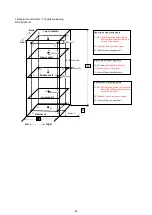
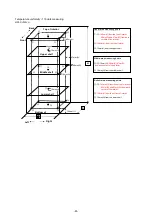
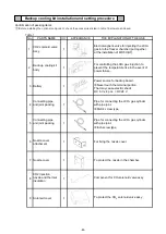
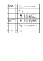

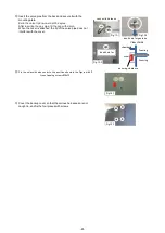

BACKUP COOLING KIT INSTALLATION
②
Unravel the bundled harness
Harness UB_BATTRY_1
R,BL
3P-3P
Harness MAIN_UBK
BL,R,OR.BU.Y.W
6P-6P,3P
Harness UB_VALVE_1
Y,G
2P-2P
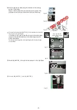
③
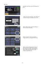
Remove the product unit cover R and the switch box cover
④
Wire harnesses through wire saddles as shown in the figure.
⑤
・
Wire harness UB_BATTRY_1 through wire saddle
②
through
wire saddle
①
.
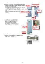
While lightly inserting the back-up cooling kit body into the installation position of the product, wire harnesses through
the wire saddle and wire as shown in the figure.
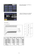
・
Wire harness MAIN_UBK is passed through the wire saddles
⑤
to
⑥
in order, and connected to the CN 14 of the main board.
Wire harness UB_VALVE_1 in the order of wire saddle
③
→
④
→
⑤
→
⑥
→
⑦
, and connect it to the harness UB_VALVE _ 2
that comes out from the bottom of the cabinet.
・
Wire the gas sensor as shown by the dotted line and set it free
toward the upper part of the power supply box.
Fix the four marking parts in the right figure with the truss head
screws M4x6.
switch box cover
unit cover-R
installation position for
backup cooling kit body
installation position for battery
CN14
wire harness
Fig.2-1
Fig.3-1
Fig.3-2
Fig.5-1
-66-
Содержание MDF-DU502VH
Страница 8: ...Dimension MDF DU502VH 5 ...
Страница 9: ...MDF DU702VH 6 ...
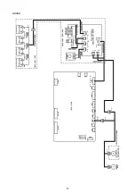
Страница 17: ...Wiring Diagram 14 ...
Страница 18: ...main Circuit Diagram 15 ...
Страница 19: ...power 16 ...
Страница 20: ...USB 17 ...
Страница 73: ...WIRING YG Y Y GR B G W W W Y G R BL Y W R R BL R OR B BL R OR B Y W Y G Y G R BL 70 ...


