


First at 2500 rpm,
Return to 3000 rpm with cascade temperature below -20 ° C
⑥
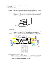
Transition conditions from the initial startup period to the constant-speed initial period (OR)
・
Initial startup period has passed 120 sec or more
・
Other than the conditions below
Extended for 30 sec when the cascade temp. is higher than the threshold (-10 ° C) and the cascade temp.
drop detection.
During the startup period, if the ambient temp. is 32 ° C or more, increase the H rotation to 4000 rpm
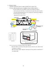
⑦
Transition conditions to constant speed initial period or constant speed period
・
Detect maximum peak value of the cascade temp. and it is -30
℃
or less.
【
Error handling
】
If the following conditions occur, reset the microcomputer once
・
Command failure occurred 20 times consecutively
If the above condition occurs even after resetting the microcomputer, it outputs a communication failure
warning.
If the communication failure is canceled, the alarm is canceled.
【
Addition
】
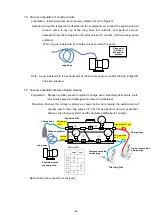
If the following condition (AND) under the constant speed period and the forced-ON mode,
change the L side rotational speed from 3000 to 3150.
・
Set temp. is -86 °C or less
・
Chamber temp. is -83 °C or less
(return to 3000 rpm at -82 °C over)
If the following conditions, change the rotation speed during PID control from 3000 to 3150.
・
Set temp. is -83 °C or less
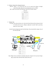
3.
Fan control
(1)
Control
The fan is operated in the following mode against the compressor operation.
table
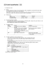
FAN operation mode
Name
Operation
Condition
A_ON
Fan is always On
When On is set by FAN control
※
1
A_OFF
Fan is always Off
When Off is set by FAN control
※
1
AUTO
Change control according to ambient
temp.
Normal
When Auto is set by FAN control
※
1
Temporary setting in manufacturing process and service work.
Then,
t
he state transition of AUTO mode is shown in the table below.
・
FAN_OFF
:
31
℃
(
Ambient temp. measurement value
)
FAN_ON
:
32
℃
(
Ambient temp. measurement value
)
①
AUTO mode
FAN_ON
≦
T
both A and B,ON
FAN_OFF<T<FAN_ON
refer to
※
2
T
≦
FAN_OFF
Link with comp.
Table AUTO mode
State
Chamber temp.(T)
No.
FAN
T
≦
FAN_OFF
FAN_OFF<T<FAN_ON
FAN_ON
≦
T
C11
Stop
Link with H comp.
※
2
※
2
ON C12
C12
Run
Link with H comp.
※
2
※
2
(none
) ―
Control policy
Link with H comp.
※
2
none
Always ON
※
2
If it does not match either state of link with comp. or AB_ON, it is compatible with comp.
-27-
Содержание MDF-DU502VH
Страница 8: ...Dimension MDF DU502VH 5 ...
Страница 9: ...MDF DU702VH 6 ...
Страница 17: ...Wiring Diagram 14 ...
Страница 18: ...main Circuit Diagram 15 ...
Страница 19: ...power 16 ...
Страница 20: ...USB 17 ...
Страница 73: ...WIRING YG Y Y GR B G W W W Y G R BL Y W R R BL R OR B BL R OR B Y W Y G Y G R BL 70 ...


