⑥
⑦
⑧
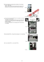
Route UB_BATTRY_ 2 through the two clampers on the right figure.
⑨
Connect UB_BATTRY_1 and UB_BATTRY_2.
Connect the harness UB_BATTRY_2 to the position marked with
the square in the right figure.
In the figure on the right, connect the red wire to the solid square
marker portion and the black wire to the dotted square marker
portion respectively.
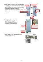
Fix the four marking parts in the right figure with the truss head
screws M4x6.
Wire the gas sensor cable using the clampers on the marking
section on the bellow.
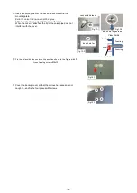
Remove CAP A attached to the base and wire the cable of the
gas sensor from the hole of the base to the back of the body.
CAP A
circle
:
the hole for
screws of back-up kit
battery
Fig.6-1
Fig.6-2
Fig.6-3
Fig.7-1
Fig.7-2
Fig.8-1
Fig.9-1
-67-
Содержание MDF-DU502VH
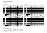
Страница 8: ...Dimension MDF DU502VH 5 ...
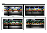
Страница 9: ...MDF DU702VH 6 ...
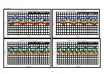
Страница 17: ...Wiring Diagram 14 ...
Страница 18: ...main Circuit Diagram 15 ...
Страница 19: ...power 16 ...
Страница 20: ...USB 17 ...
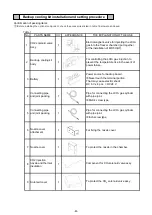
Страница 73: ...WIRING YG Y Y GR B G W W W Y G R BL Y W R R BL R OR B BL R OR B Y W Y G Y G R BL 70 ...

