89
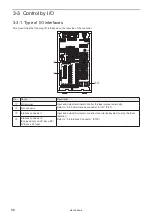
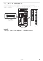
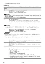
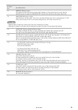
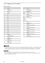
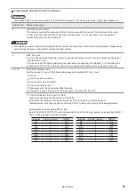
3-3-3 Signals on input/output terminal
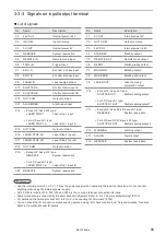
List of signals
No.
Name
Description
X1
24V OUT
Internal power +24V
X2
IN COM.
Input common
X3
0V OUT
Internal power 0V
X4
RESERVE
System reservation
X5
REMOTE IN
Remote mode input
X6
TRIG. IN
Trigger input
X7
ENC. A
Encoder A phase input
X8
ENC. B
Encoder B phase input
X9
LASER IN
Laser pumping input
X10
SHUTTER A
Shutter control input A
X11
SHUTTER B
Shutter control input B
X12
OUT COM.
Output common
X13
ALARM RES.
Alarm reset input
X14
• Except LP-Sxxx-LS1 type:
LASER STOP 1
Laser stop 1 input
• For LP-Sxxx-LS1 type:
LASER STOP 1A
Laser stop 1 input A
X15
OUT COM.
Output common
X16
LASER STOP 2A
Laser Stop 2 Input A
X17
LASER STOP 2B
Laser Stop 2 Input B
X18
OUT COM.
Output common
X19
• Except LP-Sxxx-LS1 type:
RESERVE
System reservation
• For LP-Sxxx-LS1 type:
LASER STOP 1B
Laser stop 1 input B
X20 RESERVE
System reservation
No.
Name
Description
Y1
0V OUT
Internal power 0V
Y2
OUT COM.
Output common
Y3
24V OUT
Internal power +24V
Y4
STAND BY
Standby output
Y5
REMOTE OUT
Remote mode output
Y6
READY
Marking ready output
Y7
MARKING
Marking output
Y8
MARK END
Marking end output
Y9
LASER OUT
Laser pumping
completion output
Y10
• Except LP-Sxxx-LS1 type:
SHUTTER OUT
Shutter opening output
• For LP-Sxxx-LS1 type:
SHUTTER 1 OUT
Shutter opening output 1
Y11
• Except LP-Sxxx-SF/LP-Sxxx-LS1 type:
RESERVE
System reservation
• For LP-Sxxx-SF/LP-Sxxx-LS1 type:
SHUTTER 2 OUT
Shutter opening output 2
Y12
WARNING
Warning output
Y13
ALARM
Alarm output
Y14
RESERVE
System reservation
ンㄆㄇㄆㄓㄆㄏㄆ
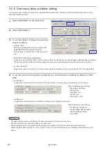
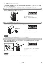
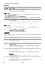
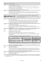
• Use the internal power (X1, X3, Y1, Y3) as the power supply when operating the laser marker alone. Do not connect
anything when using the external power supply.
• OUT COM. terminals of Y2, X12, X15 and X18 are the common terminal connected internally.
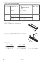
• Some terminals are connected by the short bars with shipment. Refer to “3-4-1 Factory default wiring” (P.102).
• For details on the terminal connection, refer to “3-4 Connecting I/O Terminals” (P.102).
• You can check the I/O connection status and its operation using “I/O check monitor” and “Output simulation” functions.
Refer to Operation Manual for details.
ME-LPS-SSM-8
Содержание LP-S Series
Страница 15: ...15 MEMO ME LPS SSM 8 ...
Страница 26: ...26 Chapter 1 Specification ME LPS SSM 8 ...
Страница 41: ...41 Chapter 2 Preparation ME LPS SSM 8 ...
Страница 78: ...Chapter 3 Connection for External Control ME LPS SSM 8 ...
Страница 126: ...Chapter 4 Maintenance ME LPS SSM 8 ...
Страница 148: ...Troubleshooting ME LPS SSM 8 ...
Страница 169: ...Index ME LPS SSM 8 ...
Страница 172: ...172 MEMO No 9000 0066 16V ME LPS SSM 8 ...
Страница 173: ...No 9000 0066 16V ...

