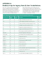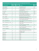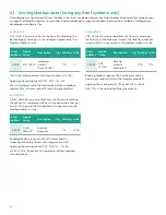
Chapter 4. Installation and maintenance
4.1 Power distribution
Installation and startup must only be carried out by qualified
personnel. The relevant country-specific electrical safety
codes and regulations (e.g., VDE, DIN) must be observed.
Before startup it is important to ensure that:
• The mains have been connected correctly and adequate
protection is provided against electric shock.
• The device can be switched off outside the power supply
according to EN 60950 regulations (e.g., by the line
protection on the primary side).
• All supply lines have sufficient fuse protection and are the
correct size.
• All output cables are the correct size for the maximum
device output current or have separate fuse protection.
• Adequate convection is available.
After installation the terminal area must be covered to
provide sufficient protection against unauthorized access
to live parts. This is ensured by installing the system in the
control cabinet or distributor box. For reliable and safe-to-
touch connections strip 7 mm (0.28 in.) from the connector
ends. The following cable cross sections can be used
(copper wiring recommended):
1
4
2
3
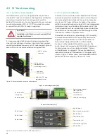
Figure 29: Phoenix Contact MINI-PS-100-240AC/24DC/C2LPS
I/O connections
4.1.1 Input
(1, figure 29)
The 100 - 240 V AC connection is made using the L and N
screw connections. The power supply in the top module
can be connected to single-phase AC networks or to
two external conductors for 3-phase networks (TN, TT or
IT network according to VDE 0100 T300/IEC364-3) with
nominal voltages of 100 - 240 V AC. The device must be
installed according to the specifications of EN 60950. It
must be possible to switch off the device using a suitable
disconnecting device outside the power supply. Note that
an all-pole disconnecting device must be provided for
2-phase operation using two external conductors for a
3-phase network. For this, line protection on the primary
side, for example, is suitable. Further device protection is not
required, as an internal fuse is present.
4.1.2 Output
(2, figure 29)
The power supply unit meets the requirements of NEC
Class 2. The 24 V DC connection is made using the “+”
and “-” screw connections on the screw connection 2. The
output voltage set upon delivery is 24 V DC and can be
adjusted from 22.5 to 26 V DC on the potentiometer 4. The
device is electronically short-circuit-proof and idling-proof.
In the event of an error, the output voltage is limited to a
maximum of 35 V DC. It should be ensured that all output
cables are the correct size for the maximum output current
or have separate fuse protection. The cable cross sections
in the secondary circuit should be large enough to keep the
voltage drops on the cables as low as possible.
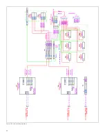
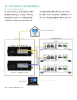
4.1.3 Wiring diagram
The control requires a single or redundant power source(s)
and safety ground connection. While the Ethernet switches
have built-in terminals to accept two redundant diode-
OR’d inputs of 18–36 V DC, the DPU’s are powered though a
separate diode redundancy module. See detailed wiring
diagram in figure 30 below for more details.
CAUTION!
Make sure all electrical connections are
correct and secure.
Solid
[mm2]
Stranded
[mm2]
AWG
Torque
[Nm]
Torque
[lb in]
1 – Input
0.2 - 2.5
0.2 - 2.5
25 - 14
0.5 - 0.6
4.4 - 5.3
2 – Output
0.2 - 2.5
0.2 - 2.5
25 - 14
0.5 - 0.6
4.4 - 5.3
3 – Signal
0.2 - 2.5
0.2 - 2.5
25 - 14
0.5 - 0.6
4.4 - 5.3
Table 8: Wiring specification for MINI 24 VDC power supply
37
Содержание flare.IQ Generation 2
Страница 1: ...flare IQ Generation 2 Operation and maintenance manual...
Страница 2: ...2...
Страница 3: ...flare IQ Generation 2 Operation and maintenance manual 910 350 rev A June 2020 3...
Страница 4: ...no content intended for this page 4...
Страница 38: ...Figure 30 System wiring diagram 38...
Страница 48: ...48...
Страница 49: ...no content intended for this page 49...


