3.4 Modbus
3.4.1 Modbus configuration
The default Modbus TCP configuration is as follows:
Modbus device address = 1
TCP port = 502
Byte order = most significant byte first
Word order = most significant word first
This configuration can be changed as required on the
network page of the web console.
3.4.2 Modbus address list
flare.IQ Gen 2 uses 32-bit IEEE-754 floating point
representation for all analog inputs (Modbus holding
registers) and outputs (Modbus Input registers). Hence, no
scaling is required to maintain numerical accuracy.
Holding registers should be written using the Modbus
preset multiple registers command (function code 16). All
32-bit values must be sent as an even number of registers
(minimum 2) with an even starting address. flare.IQ register
addressing is zero-based. The first Modbus register is
address 0000. Some DCS configurations use ones-based
addressing, where the first Modbus register is address 0001.
In this case, address values may have to be corrected by
adding/subtracting 1.
Many of the Modbus values are also displayed on the web
console. For these critical parameters, the web console can
be used to verify that Modbus data from the DCS is being
sent to the correct register in the correct format. Extreme
numeric values, ‘INF’, or ‘NaN’ displayed on the web console
are an indication of incorrectly formatted Modbus data.
A signal is considered bad quality when its link to Modbus is
broken, the signal value is unchanging, or the signal is out
of range. In these cases, the signal value is held at the last
known good value. Additionally, the flare.IQ will validate
that inputs are reasonable; for example, if the total
concentration of all specified composition gases exceeds
100%, the signal values of all gases will be set to bad quality
until the composition is corrected.
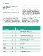
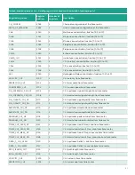
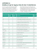
The list of Modbus addresses of analog inputs (holding
registers) used for flare control is shown in table 3 below.
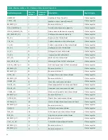
Table 4 shows all holding registers required for digital
verification while table 5 lists all analog outputs (Input
registers) for flare control. Table 6 provides the addresses
for all Boolean status and coil registers.
Table 3: Modbus address list - holding registers for flare control (analog inputs)
Register tag name
Register
address
Number of
registers
Description
AR
1010
2
Argon concentration, fraction (0.0 to 1.0)
CO2
1012
2
Carbon dioxide concentration, fraction (0.0 to 1.0)
CO
1014
2
Carbon monoxide concentration, fraction (0.0 to 1.0)
H2
1016
2
Hydrogen concentration, fraction (0.0 to 1.0)
N2
1018
2
Nitrogen concentration, fraction (0.0 to 1.0)
O2
1020
2
Oxygen concentration, fraction (0.0 to 1.0)
H2O
1022
2
Water vapor concentration, fraction (0.0 to 1.0)
MW_INPUT
1030
2
Molecular weight from GC/MS
NHVVG_INPUT
1032
2
Net heating value of vent (flare) gas
QFUEL_TC
1040
2
Fuel gas flow rate
QFLARE_TC
1050
2
Flare flow rate
TFLARE_TC
1052
2
Flare temperature
PFLARE_TC
1054
2
Flare pressure
CFLARE_TC
1056
2
Flare sound speed
QSTEAM_TC
1060
2
Steam flow rate
TSTEAM_TC
1062
2
Steam temperature (future use)
29
Содержание flare.IQ Generation 2
Страница 1: ...flare IQ Generation 2 Operation and maintenance manual...
Страница 2: ...2...
Страница 3: ...flare IQ Generation 2 Operation and maintenance manual 910 350 rev A June 2020 3...
Страница 4: ...no content intended for this page 4...
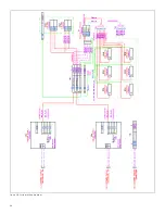
Страница 38: ...Figure 30 System wiring diagram 38...
Страница 48: ...48...
Страница 49: ...no content intended for this page 49...


